Universal Switching Module Enhanced
The
The values you can view with the cnfbusbw and dspbusbw commands are:
•Minimum Required Bandwidth, the necessary bandwidth that switch software has calculated for the existing connections on the local
•Average Used Bandwidth is the average bandwidth usage.
•Peak Used Bandwidth is the peak bandwidth usage.
•Maximum Port Bandwidth is the maximum bandwidth that the back card can support. The FastPackets per second field has a
•Allocated Bandwidth is the current cellbus allocation for the card. The field shows the UBUs, the bandwidth when only ATM cells are on the bus, and cells plus Fastpackets. The reason for cells alone and cells plus Fastpackets is that cells can exist on the cellbus with or without FastPackets. The last field under Allocated Bandwidth shows the formula to which the allocated values must adhere. (A description of the formula follows the example screen.)
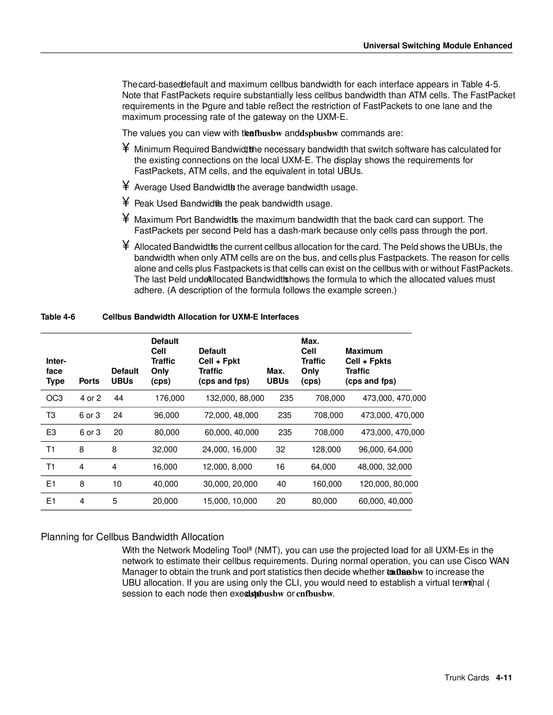
Table |
| Cellbus Bandwidth Allocation for |
|
| |||
|
|
|
|
|
|
|
|
|
|
| Default |
|
| Max. |
|
|
|
| Cell | Default |
| Cell | Maximum |
Inter- |
|
| Traffic | Cell + Fpkt |
| Traffic | Cell + Fpkts |
face |
| Default | Only | Traffic | Max. | Only | Traffic |
Type | Ports | UBUs | (cps) | (cps and fps) | UBUs | (cps) | (cps and fps) |
|
|
|
|
|
|
|
|
OC3 | 4 or 2 | 44 | 176,000 | 132,000, 88,000 | 235 | 708,000 | 473,000, 470,000 |
|
|
|
|
|
|
|
|
T3 | 6 or 3 | 24 | 96,000 | 72,000, 48,000 | 235 | 708,000 | 473,000, 470,000 |
|
|
|
|
|
|
|
|
E3 | 6 or 3 | 20 | 80,000 | 60,000, 40,000 | 235 | 708,000 | 473,000, 470,000 |
|
|
|
|
|
|
|
|
T1 | 8 | 8 | 32,000 | 24,000, 16,000 | 32 | 128,000 | 96,000, 64,000 |
|
|
|
|
|
|
|
|
T1 | 4 | 4 | 16,000 | 12,000, 8,000 | 16 | 64,000 | 48,000, 32,000 |
|
|
|
|
|
|
|
|
E1 | 8 | 10 | 40,000 | 30,000, 20,000 | 40 | 160,000 | 120,000, 80,000 |
|
|
|
|
|
|
|
|
E1 | 4 | 5 | 20,000 | 15,000, 10,000 | 20 | 80,000 | 60,000, 40,000 |
|
|
|
|
|
|
|
|
Planning for Cellbus Bandwidth Allocation
With the Network Modeling Tool™ (NMT), you can use the projected load for all
Trunk Cards