Network Trunk Module
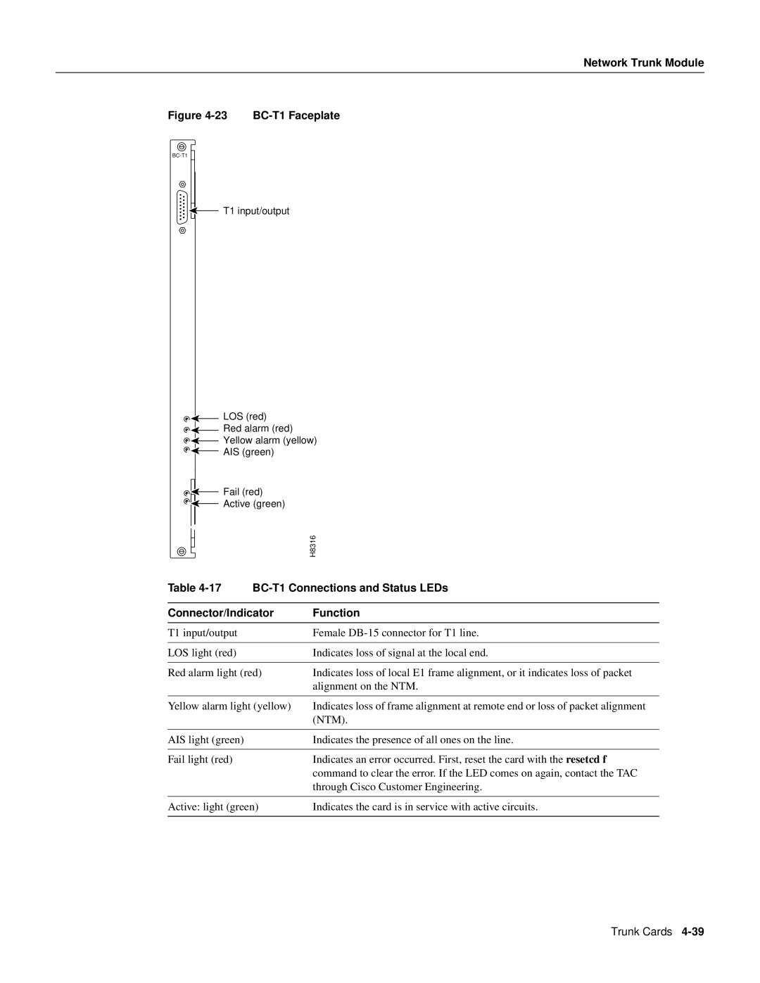
Figure 4-23 BC-T1 Faceplate
![]()
![]()
![]() T1 input/output
T1 input/output
|
|
|
| LOS (red) |
|
|
|
|
|
| |
|
|
|
| Red alarm (red) |
|
|
|
|
|
| |
|
|
|
| Yellow alarm (yellow) | |
|
|
|
| ||
|
|
|
| AIS (green) |
|
|
|
|
|
| |
|
|
|
| Fail (red) |
|
|
|
|
|
| |
|
|
|
|
| |
|
|
|
|
| |
|
|
|
| Active (green) | H8316 |
|
|
|
| ||
|
|
|
|
| |
|
|
|
|
| |
|
|
|
|
| |
|
|
|
|
| |
Table |
| ||||
|
|
|
|
| |
Connector/Indicator | Function | ||||
|
|
|
|
| |
T1 input/output | Female | ||||
|
|
|
|
| |
LOS light (red) | Indicates loss of signal at the local end. | ||||
|
|
|
|
| |
Red alarm light (red) | Indicates loss of local E1 frame alignment, or it indicates loss of packet | ||||
|
|
|
|
| alignment on the NTM. |
|
|
|
|
| |
Yellow alarm light (yellow) | Indicates loss of frame alignment at remote end or loss of packet alignment | ||||
|
|
|
|
| (NTM). |
|
|
|
|
| |
AIS light (green) | Indicates the presence of all ones on the line. | ||||
|
|
|
|
| |
Fail light (red) | Indicates an error occurred. First, reset the card with the resetcd f | ||||
|
|
|
|
| command to clear the error. If the LED comes on again, contact the TAC |
|
|
|
|
| through Cisco Customer Engineering. |
|
|
|
|
| |
Active: light (green) | Indicates the card is in service with active circuits. | ||||
|
|
|
|
|
|
Trunk Cards