Universal Switching Module Enhanced
Determining the UXM-E’s Mode of Operation
The UXM-E detects reports its mode of operation to switch software when you first activate either a trunk to the network or a line on the UNI or NNI. If you activate a trunk, the UXM-E goes into trunk mode. If you activate a line, the UXM-E goes into port mode. The CLI commands for these operations are uptrk and upln, respectively. (The UXM-E description in this chapter lists important information about the commands that apply to the UXM-E, but the order of their use appears in the Cisco IGX 8400 Series Installation guide. For a detailed description of each command and its parameters, see the Cisco WAN Switching Command Reference.)
Example Networks with UXM-Es
Networks with both trunk mode and port mode UXM-Es appear in Figure 4-1and Figure 4-2,respectively. The nodes in Figure 4-1use only UXM-Es for port interfaces and trunk interfaces. Figure 4-2shows a variety of cards providing interfaces for different traffic types.
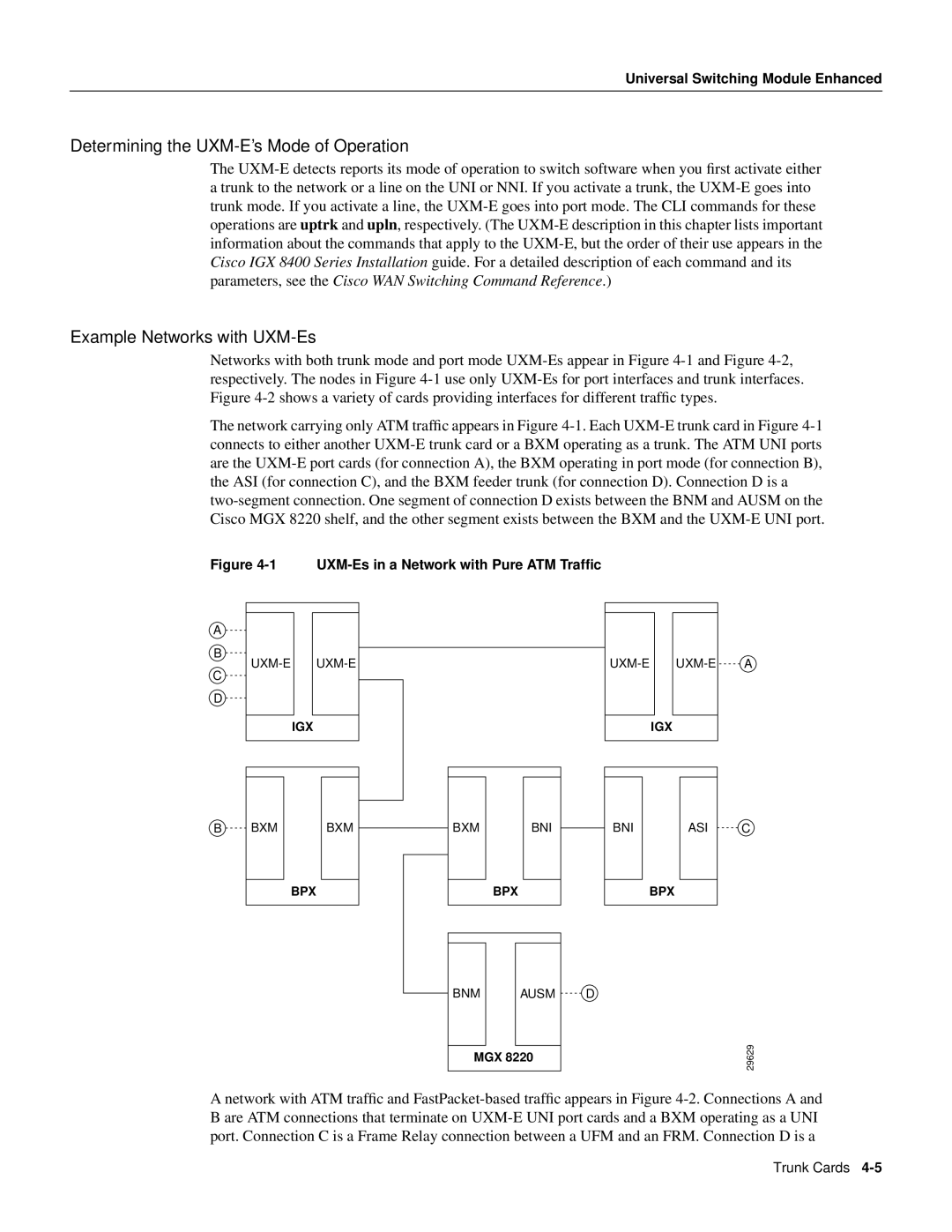
The network carrying only ATM traffic appears in Figure 4-1.Each UXM-E trunk card in Figure 4-1connects to either another UXM-E trunk card or a BXM operating as a trunk. The ATM UNI ports are the UXM-E port cards (for connection A), the BXM operating in port mode (for connection B), the ASI (for connection C), and the BXM feeder trunk (for connection D). Connection D is a two-segment connection. One segment of connection D exists between the BNM and AUSM on the Cisco MGX 8220 shelf, and the other segment exists between the BXM and the UXM-E UNI port.
Figure 4-1 UXM-Es in a Network with Pure ATM Traffic
A network with ATM traffic and FastPacket-based traffic appears in Figure 4-2.Connections A and B are ATM connections that terminate on UXM-E UNI port cards and a BXM operating as a UNI port. Connection C is a Frame Relay connection between a UFM and an FRM. Connection D is a