Universal Switching Module Enhanced
Calculating Cellbus Bandwidth Changes
To determine how many UBUs are necessary, use the values for average bandwidth used in the following formula:
fps
------- + cps 2
UBUs = -----------------------
4000
In most circumstances, the fps and cps values from average bandwidth used are sufficient. The peak bandwidth used values are primarily informational.
The information in Table
When you use dspbusbw, a yes/no prompt asks if you want firmware to retrieve the usage values. If you enter a “y,” the
If you enter an “n,” switch software displays the current values that reside in control card memory (on the NPM). The values in memory come from the last update from the
ATM Across a Public ATM Network
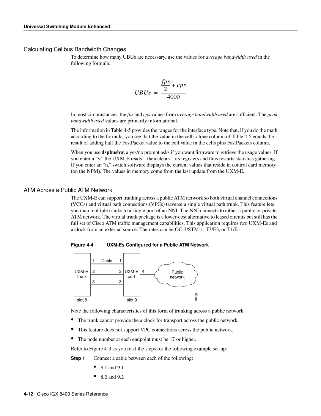
The
Figure 4-4 UXM-Es Configured for a Public ATM Network
| 1 | Cable 1 |
|
|
|
2 | 2 | 4 | Public | ||
trunk | 3 | 3 | port |
| network |
|
|
|
| ||
|
|
|
|
|
|
slot 8 |
| slot 9 |
| ||
10106
Note the following characteristics of this form of trunking across a public network:
•
•
•
The trunk cannot provide the a clock for transport across the public network.
This feature does not support VPC connections across the public network.
The node number at each endpoint must be 17 or higher.
Refer to Figure
Step 1 Connect a cable between each of the following:
•8.1 and 9.1
•8.2 and 9.2
