Manuals
/
Cisco Systems
/
Computer Equipment
/
Network Router
Cisco Systems
IGX 8400
manual
UXM-E Front Card
Models:
IGX 8400
1
8
46
46
Download
46 pages
63.41 Kb
5
6
7
8
9
10
11
12
Connector/Indicator Function
Maintenance
UXM-E Trunk Features
UXM-E in Trunk Mode
Page 8
Image 8
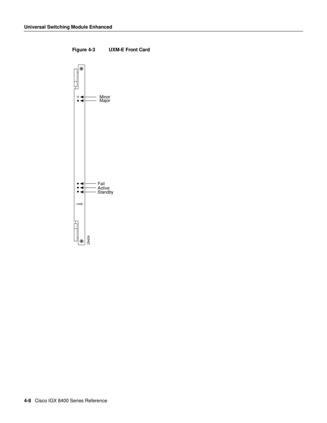
Universal Switching Module Enhanced
Figure
4-3
UXM-E
Front Card
Minor
Major
Fail
Active
Standby
UXME
29424
4-8
Cisco IGX 8400 Series Reference
Page 7
Page 9
Page 8
Image 8
Page 7
Page 9
Contents
Trunk Cards
Trunk Interface Cards
Trunk Front Cards Card Acronym Card Name
Loopback Test
Trunk Card Maintenance
Trunk Operating Modes
Introduction to the UXM-E Trunk Mode
Universal Switching Module Enhanced
Determining the UXM-E’s Mode of Operation
Example Networks with UXM-Es
UXM-E Trunk Features
UXM-Es in a Network with Heterogeneous Traffic
Card Name Card Description
UXM-E Interfaces
Back Cards for the UXM-E
UXM-E Front Card
Switchover to a Redundant UXM-E
Maximum Number of UXM-Es
Cabled UXM-E Redundancy
UXM-E Status LEDs Fail Active Standby Status of Card
UXM-E as a Clock Source
Cellbus Bandwidth Usage
Card Mismatch
Planning for Cellbus Bandwidth Allocation
OC3
Calculating Cellbus Bandwidth Changes
ATM Across a Public ATM Network
UXM-E in Trunk Mode
Routing over Cell Trunks Only
Types of Supported Traffic
Traffic from FastPacket-Based Cards Traffic Type
Types of Connections on a UXM-E Trunk
Inverse Multiplexing over ATM on IGX Trunks
Adding an IGX Feeder
Adding and Removing IMA Group Links
Line Redundancy
IMA Protocol
Two-Segment Connections
Routing Feeder Connection Cell Endpoint a Endpoint B Type
Gateway Type Routing Load Type
Three-Segment Connections
Feeder Connection Cell Endpoint a Endpoint B Type
RT-VBR Gwtypenone
ABR.FST Gwtypenone
OC3 STM1 SMF
Activation and Configuration of a UXM-E in Trunk Mode
UXM-E Atfr
20Cisco IGX 8400 Series Reference
Alarms for Physical Lines and Logical Trunks
SCR and PCR Policing at Less than 50 CPS on UXM-E
BXM
IGX-UXM-E
Trunk Statistics for Troubleshooting
10 PCR Policing Application Example
Summary Statistics
UXM-E Interface Cards
OC-3/STM1 Back Cards
Connectors and LEDs for SMF and MMF Back Cards
Connector/Indicator Function
11 BC-UAI-4-155-SMF Faceplate
T3 Back Cards
12 BC-UAI-2-155-SMF Faceplate
BC-UAI-6-T3 Faceplate
Connectors and LEDs for BC-UAI-6-T3 and BC-UAI-3-T3
Connectors/Indicator Function
E3 Back Cards
14 BC-UAI-3-T3 Faceplate
Connectors and LEDs for BC-UAI-6-E3 and BC-UAI-3-E3
BC-UAI-6-E3 Faceplate
T1 Back Cards
16 BC-UAI-3-E3 Faceplate
BC-UAI-8-T1-DB-15 Faceplate
E1 Back Cards
18 BC-UAI-4-T1-DB-15 Faceplate
BC-UAI-8-E1 DB-15 Faceplate
Port
21 BC-UAI-4-E1 DB-15 Faceplate
22 BC-UAI-4-E1 BNC Faceplate
Network Trunk Module
Cable Redundancy for the NTM
NTM Status
T1 Interface Card BC-T1
BC-T1 Faceplate Description
23 BC-T1 Faceplate
BC-T1 Connections and Status LEDs
E1 Interface Back Card BC-E1
BC-E1 Connections and Status LEDs
RX-TX
Subrate Interface Card BC-SR
Connection/Indicator Function
BC-SR Connections and Status LEDs
Y1 Interface Back Card BC-Y1
TX MON
BC-Y1 Connections and Status LEDs
RX MON
46Cisco IGX 8400 Series Reference
Top
Page
Image
Contents