Router Platform User Interface Reference
Dhcp Policy Page, page K-167 NTP Policy Page, page K-174
CPU Policy Page, page K-107
Chapter K, Router Platform User Interface Reference
NAT Page-Interface Specification Tab
NAT Policy
For more information, see NAT on Cisco IOS Routers,
Related Topics
Edit Interfaces Dialog Box-NAT Inside Interfaces
Field Reference
Edit Interfaces Dialog Box-NAT Outside Interfaces
NAT Page-Static Rules Tab
Information, see Filtering Tables,
NAT Static Rule Dialog Box
Disabling the Payload Option for Overlapping Networks,
Basic Interface Settings on Cisco IOS Routers,
Defining Static NAT Rules,
Disabling the Alias Option for Attached Subnets,
Table K-5 NAT Static Rule Dialog Box
Table K-5 NAT Static Rule Dialog Box
Appendix K Router Platform User Interface Reference
NAT Page-Interface Specification Tab, page K-3
NAT Page-Dynamic Rules Tab
For more information, see Defining Dynamic NAT Rules,
NAT Dynamic Rule Dialog Box
F-593
Object Selectors, page F-593
NAT Page-Timeouts Tab
Specifying NAT Timeouts,
Router Interfaces
Create Router Interface Dialog Box
Table Columns and Column Heading Features,
Enabled Type Name Parent
BRI, PRI Isdn
Discontiguous Network Masks,
Table K-10 Create Router Interface Dialog Box
MTU
Vlan ID
Dlci
Interface Auto Name Generator Dialog Box
Advanced Interface Settings
CDP
Available Interface Types,
Advanced Interface Settings Dialog Box
You can create an interface role object
Eguide09186a00804247fc.html
Selectors, page F-593
For more information, see Understanding Helper Addresses,
Cisco Discovery Protocol settings
Table K-13 Advanced Interface Settings Dialog Box
Fragreassmps6441TSDProductsConfigurationGuideChapter.html
VFR
00800a3ded.shtml
ACL
AIM-IPS Interface Settings
IPS Monitoring Information Dialog Box
Dialer Policy
Configuring Dial Backup,
Dialer Profile Dialog Box
SPID1
SPID2
Table K-17 Dialer Profile Dialog Box
Dialer Physical Interface Dialog Box
Isdn BRI
Adsl Policy
Adsl on Cisco IOS Routers,
Defining Adsl Settings, PVC Policy Page, page K-54
Adsl Settings Dialog Box
Supported by each card type may cause deployment to fail
Table K-20 Adsl Settings Dialog Box
Shdsl Policy
Edit the selected DSL controller definition
Shdsl on Cisco IOS Routers,
Shdsl Controller Dialog Box
Defining Shdsl Controllers,
Dialog Box, page K-53
User Guide for Cisco Security Manager
CPE
Table K-22 Shdsl Dialog Box
Controller Auto Name Generator Dialog Box
PVC Policy
OAM-PVC
PVC ID
PVC
PVC OAM
Defining ATM PVCs,
PVC Dialog Box
Table K-25 PVC Dialog Box
PVC Dialog Box-Settings Tab, page K-59
PVC. See PVC Dialog Box-QoS Tab, page K-63
Inverse ARP. See PVC Dialog Box-Protocol Tab, page K-67
PVC Dialog Box-Settings Tab
VPI
VCI
Ilmi
PVC
Resources are freed for other dial-in users
PVC Dialog Box-QoS Tab
Dialog Box-Protocol Tab, page K-67
PPP
Understanding Policing and Shaping Parameters,
Quality of Service Policy Page, page K-199
Service Classes,
ABR
CBR
VBR-RT
UBR
UBR+
VBR-NRT
PVC Dialog Box-Protocol Tab
PVC Dialog Box, page K-56 Defining ATM PVCs,
Define Mapping Dialog Box
Type for the PVC. See PVC Dialog Box-Settings Tab, page K-59
PVC Advanced Settings Dialog Box
Go to the PVC Dialog Box, page K-56, then click Advanced
PVC Advanced Settings Dialog Box-OAM Tab
Advanced Settings Dialog Box-OAM Tab, page K-70
Advanced Settings Dialog Box-OAM-PVC Tab, page K-73
PVC Dialog Box, page K-56
Table K-31 PVC Advanced Settings Dialog Box-OAM Tab
OAM-PVC tab
PVC Advanced Settings Dialog Box-OAM-PVC Tab
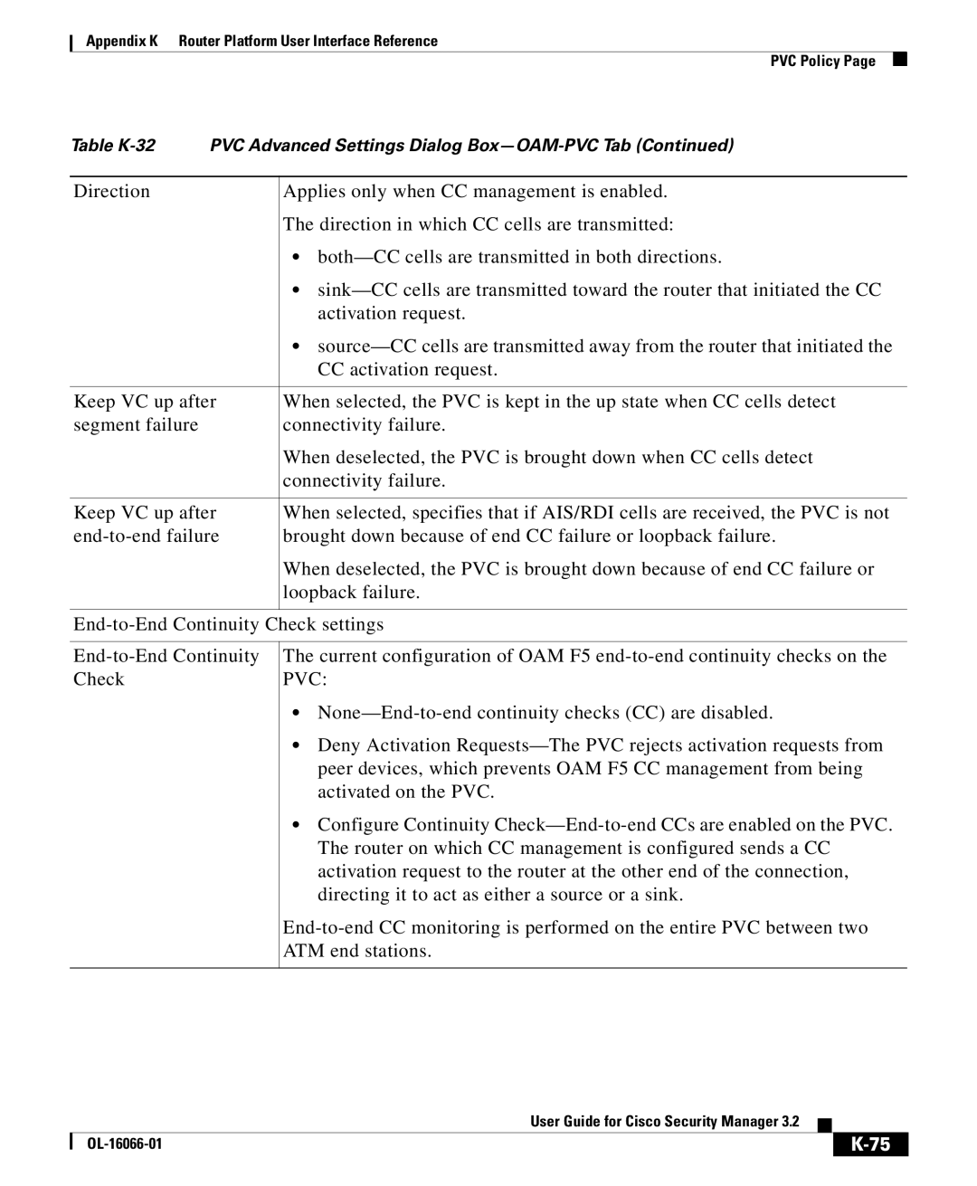
Table K-32 PVC Advanced Settings Dialog Box-OAM-PVC Tab
Table K-32 PVC Advanced Settings Dialog Box-OAM-PVC Tab
PPP/MLP Policy
Table K-33 PPP/MLP
Defining PPP Connections,
PPP Dialog Box
Connection. See PPP Dialog Box-PPP Tab, page K-80
PPP Dialog Box-PPP Tab
Tab, page K-84
PPP Dialog Box-MLP Tab, page K-84
Table K-35 PPP Dialog Box-PPP Tab
It for other PPP connections on this device
Chap Authentication settings
PPP Dialog Box-MLP Tab
PPP Dialog Box-PPP Tab, page K-80
MLP
Advance
None-Negotiation is conducted without using an endpoint
AAA Policy
Defining AAA Services,
AAA Page-Authentication Tab
Predefined AAA Authentication Server Groups,
Understanding Method Lists,
AAA Server Group Dialog Box, page F-12
AAA Page-Authorization Tab
Information, see Filtering Tables,
Command Authorization Dialog Box
AAA Page-Accounting Tab
Table K-41 AAA Page-Accounting Tab
See description Table N-91 on page N-131
Command Accounting Dialog Box
Server groups configured with TACACS+
Accounts and Credential s Policy
Table K-43 Accounts and Credentials
100
User Account Dialog Box
MD5
Understanding FlexConfig Objects,
Defining Accounts and Credential Policies,
User Accounts and Device Credentials on Cisco IOS Routers,
Bridging Policy
Bridging on Cisco IOS Routers,
102
103
Bridge Group Dialog Box
104
Clock Policy
105
106
107
CPU Policy
108
109
110
Http Policy
Http Page-Setup Tab
Http and Https on Cisco IOS Routers,
111
Http Page-AAA Tab
Https
112
113
Http Page-Setup Tab, page K-111
114
115
116
Command Authorization Override Dialog Box
Http Policy Page, page K-110
AAA Policy Page, page K-87
117
Console Policy
Console Page-Setup Tab
VTY Line Dialog Box-Setup Tab, page K-132
118
119
120
121
Console Page-Authentication Tab
122
Page-Authentication Tab, page K-88
123
Console Page-Authorization Tab
124
125
Console Page-Accounting Tab
126
127
Page-Accounting Tab, page K-93
128
129
VTY Policy
130
131
Line Access on Cisco IOS Routers,
Dialog Box-Setup Tab, page K-132
VTY Line Dialog Box
132
VTY Line Dialog Box-Setup Tab
Defining VTY Line Setup Parameters,
Console Page-Setup Tab, page K-118
133
134
Policy. See Http Page-Setup Tab, page K-111
135
136
VTY Line Dialog Box-Authentication Tab
137
VTY Line Dialog Box-Authorization Tab
138
Page-Authorization Tab, page K-90
139
VTY Line Dialog Box-Accounting Tab
140
141
142
Command Authorization Dialog Box-Line Access
Console Policy Page, page K-117 VTY Policy Page, page K-129
143
144
Level. See Command Accounting Dialog Box, page K-96
145
Command Accounting Dialog Box-Line Access
146
147
Secure Shell Policy
148
Box-Setup Tab, page K-132
Snmp Policy
For more information, see Defining Snmp Agent Properties,
149
150
Snmp on Cisco IOS Routers,
Permission Dialog Box
Generate. See Snmp Traps Dialog Box, page K-155
151
152
Trap Receiver Dialog Box, page K-153
Snmp Traps Dialog Box, page K-155
Defining Snmp Agent Properties,
Trap Receiver Dialog Box
Permission Dialog Box, page K-151
153
154
155
Snmp Traps Dialog Box
156
For more information, see Understanding IKE,
157
158
DNS Policy
IP Host Dialog Box
DNS on Cisco IOS Routers,
159
Hostname Policy
Hostnames and Domain Names on Cisco IOS Routers,
160
For more information, see Defining Router Memory Settings,
Memory Policy
161
162
Secure Device Provisioning Policy
Secure Device Provisioning on Cisco IOS Routers,
163
Click Select to display an Object Selectors, page F-593
Administrative Introducers,
Secure Device Provisioning Workflow,
Understanding PKI Enrollment Objects,
165
166
167
Dhcp Policy
For more information, see Defining Dhcp Policies,
Dhcp on Cisco IOS Routers,
To display an Object Selectors, page F-593
Definition, page 9-153and Supported IP Address Formats,
168
169
170
Dhcp Database Dialog Box
Defining Dhcp Policies,
IP Pool Dialog Box, page K-171
171
IP Pool Dialog Box
172
Select to display an Object Selectors, page F-593
173
Ddhhmm
NTP Policy
For more information, see Defining NTP Servers,
174
175
NTP Server Dialog Box, page K-176
176
NTP Server Dialog Box
177
Policy Page, page K-174
178
K-174
802.1x Policy
For more information, see Defining 802.1x Policies,
179
Or click Add to display an Object Selectors, page F-593
Defined here. See PPP Dialog Box, page K-78
180
181
182
Network Admission Control Page-Setup Tab
Network Admission Control Policy
183
184
Defining NAC Setup Parameters,
Configuration Dialog Box, page K-187
More information, see Working with Access Rules,
185
186
Network Admission Control Page-Setup Tab, page K-183
Network Admission Control Page-Interfaces Tab
Defining NAC Interface Parameters,
187
NAC Interface Configuration Dialog Box
188
Page, page F-31
Network Admission Control Page-Identities Tab
Defining NAC Identity Parameters,
189
190
NAC Identity Profile Dialog Box
NAC Identity Profile Dialog Box, page K-190
NAC Identity Action Dialog Box
NAC Identity Action Dialog Box, page K-191
Actions, see NAC Identity Action Dialog Box, page K-191
K-187
Logging Setup Policy
Intercept ACL. See NAC Interface Configuration Dialog Box
Box, page K-190
193
194
Information, see -5 on
195
196
Syslog Servers Policy
For more information, see Defining Syslog Servers,
197
Syslog Server Dialog Box
XML
198
Understanding Network/Host Objects,
Quality of Service Policy
Defining Syslog Servers,
Logging on Cisco IOS Routers,
200
Defining QoS Policies,
Understanding Control Plane Policing,
CIR
201
202
203
Quality of Service on Cisco IOS Routers,
QoS Policy Dialog Box
K-205
204
205
QoS Class Dialog Box
206
Tab, page K-217
Box-Matching Tab, page K-208
Box-Queuing and Congestion Avoidance Tab, page K-212
Dialog Box-Policing Tab, page K-214
208
QoS Class Dialog Box-Matching Tab
209
Dscp
F-593. For more information, see Edit ACLs Dialog Box-QoS
Classes, page K-210
Edit ACLs Dialog Box-QoS Classes
Defining QoS Class Matching Parameters,
210
211
QoS Class Dialog Box-Marking Tab
212
QoS Class Dialog Box-Queuing and Congestion Avoidance Tab
213
214
QoS Class Dialog Box-Policing Tab
215
216
217
QoS Class Dialog Box-Shaping Tab
218
219
BGP Routing Policy
220
BGP Page-Setup Tab
Defining BGP Routes,
Supported IP Address Formats,
221
Dialog Box, page K-222
222
Neighbors Dialog Box
223
BGP Page-Setup Tab, page K-220
BGP Page-Redistribution Tab
Redistributing Routes into BGP,
224
BGP Redistribution Mapping Dialog Box
225
Eigrp Page-Setup Tab
Eigrp Routing Policy
226
227
Eigrp Setup Dialog Box
228
Defining Eigrp Routes,
229
Eigrp Page-Setup Tab, page K-226
Eigrp Page-Interfaces Tab
Edit Interfaces Dialog Box-EIGRP Passive Interfaces
230
Defining Eigrp Interface Properties,
Systems, see Eigrp Setup Dialog Box, page K-227
Eigrp Interface Dialog Box
231
232
Eigrp Page-Redistribution Tab
233
234
Eigrp Redistribution Mapping Dialog Box
Redistributing Routes into EIGRP,
Page-Redistribution Tab, page K-223
235
236
Ospf Interface Policy
237
238
Defining Ospf Interface Settings,
Ospf Interface Dialog Box
Ospf Routing on Cisco IOS Routers,
239
240
241
242
Objects,
Ospf Process Page-Setup Tab
Ospf Process Policy
243
244
Defining Ospf Process Settings,
245
Ospf Setup Dialog Box
Ospf Process Page-Setup Tab, page K-243
Edit Interfaces Dialog Box-OSPF Passive Interfaces
246
Defining Ospf Area Settings,
Ospf Process Page-Area Tab
247
248
Ospf Area Dialog Box
249
Ospf Process Page-Redistribution Tab
250
251
Ospf Redistribution Mapping Dialog Box
252
253
254
Ospf Max Prefix Mapping Dialog Box
Ospf Redistribution Mapping Dialog Box, page K-251
K-243
RIP Page-Setup Tab
RIP Routing Policy
255
Defining RIP Setup Parameters,
An Object Selectors, page F-593
256
RIP Page-Authentication Tab
Edit Interfaces Dialog Box-RIP Passive Interfaces
257
Defining RIP Interface Authentication Settings,
RIP Page-Setup Tab, page K-255
258
259
RIP Authentication Dialog Box
Redistribution tab. See RIP Page-Setup Tab, page K-255
RIP Page-Redistribution Tab
260
RIP Redistribution Mapping Dialog Box
Redistributing Routes into RIP,
261
262
Static Routing Policy
Static Routing on Cisco IOS Routers,
263
264
Static Routing Dialog Box
265
Defining Static Routes,
266
267
268