Cisco ONS 15600 Reference Manual
Corporate Headquarters
Cisco ONS 15600 Reference Manual, Release
N T E N T S
Iii
TSC Network-Level Indicators
SFP Modules
TSC Card Database
Path Protection Circuits
Vii
Two-Fiber Blsr to Four-Fiber Blsr
Viii
10.1 Any Service Any Port Card Application 10.2
Snmp
Bandwidth
Environmental Specifications A-4
Xii
CTC Default Settings C-39
Xiii
Xiv
Bay Label
Legal Disclaimer Tab
Xvi
Path-Protected Mesh Network Ppmn Virtual Ring
Xvii
OSI/IP Scenario 5 GNE Without an OSI DCC Connection
Xviii
B L E S
Xix
Link Icons
Alarm Window
Xxi
Power and Noise Limited Performances A-14
Xxii
About this Manual
Xxiii
Audience
Revision History
Document Objectives
Related Documentation
Xxv
Document Conventions
Convention Application
Warnung Wichtige Sicherheitshinweise
Xxvi
Xxvii
Avvertenza Importanti Istruzioni Sulla Sicurezza
Aviso Instruções Importantes DE Segurança
Xxviii
GEM Disse Anvisninger
Xxix
Xxx
Cisco Optical Networking Product Documentation CD-ROM
Where to Find Safety and Warning Information
Obtaining Optical Networking Information
Xxxi
Xxxii
Installation Overview
Shelf and Backplane Hardware
Bay Installation
ONS 15600 with Dollies Installed
Front Door
ONS 15600 Front Door
Rear Covers
Front door also has a Class I laser warning Figure
6shows the bus bar covers
Customer Access Panel
Cable Routing
Rear of the ONS 15600, Including the CAP
8shows the CAP faceplate
Visual and Audible Alarms
Alarm, Timing, LAN, and Craft Pin Connections
External Alarm and Control Contact Installation
Timing Installation
Alarm Cutoff and PDU Alarms
See , Timing, for more information
LAN Installation
4 TL1 Craft Interface Installation
Power Distribution Unit
Power and Ground Description
11 Front and Rear Bay Ground Holes
Fan-Tray Assembly
Air Filter
Fan Speed and Failure
13 Air Filter and one Fan Tray Pulled Out
Condition Watts Amps BTU/Hr
Cards and Slots
Card Slot Requirements
157
Asap Card Cables
Card Ports Line Rate per Port
OGI Cables
17show the OGI pin breakout for the OC-48 card
Card Replacement
Optical Card Cable Routing
Page
Page
Card Description For Additional Information
Card Overview
Card Summary
Card Compatibility
Card R1.0 R1.x.x R5.0 R6.0 R7.0 R7.2
TSC Slots and Connectors
TSC Card
TSC Faceplate and Block Diagram
TSC
Indicator Color Definition
TSC Card-Level Indicators
TSC Network-Level Indicators
Ssxc Card
TSC Push-Button Switches
Ssxc Switch Matrix
Push-Button Function
Ssxc Slots and Connectors
Ssxc Faceplate and Block Diagram
OC48/STM16 LR/LH 16 Port 1550 Card
Ssxc Card-Level Indicators
1 OC48/STM16 LR/LH 16 Port 1550 Slots and Connectors
2 OC48/STM16 LR/LH 16 Port 1550 Faceplate and Block Diagram
OC48/STM16 LR/LH 16 Port 1550 Faceplate and Block Diagram
5 OC48/STM16 LR/LH 16 Port 1550 Card OGI Connector Pinout
3 OC48/STM16 LR/LH 16 Port 1550 Card-Level Indicators
4 OC48/STM16 LR/LH 16 Port 1550 Network-Level Indicators
Indicator Color Description
1 OC48/STM16 SR/SH 16 Port 1310 Slots and Connectors
OC48/STM16 SR/SH 16 Port 1310 Card
2 OC48/STM16 SR/SH 16 Port 1310 Faceplate and Block Diagram
OC48/STM16 SR/SH 16 Port 1310 Faceplate and Block Diagram
5 OC48/STM16 SR/SH 16 Port 1310 Card OGI Connector Pinout
3 OC48/STM16 SR/SH 16 Port 1310 Card-Level Indicators
4 OC48/STM16 SR/SH 16 Port 1310 Network-Level Indicators
12lists the OC48/STM16 SR/SH card OGI connector pinouts
1 OC192/STM64 LR/LH 4 Port 1550 Slots and Connectors
OC192/STM64 LR/LH 4 Port 1550 Card
2 OC192/STM64 LR/LH 4 Port 1550 Faceplate and Block Diagram
OC192/STM64 LR/LH 4 Port 1550 Faceplate and Block Diagram
5 OC192/STM64 LR/LH 4 Port 1550 Card OGI Connector Pinout
3 OC192/STM64 LR/LH 4 Port 1550 Card-Level Indicators
4 OC192/STM64 LR/LH 4 Port 1550 Network-Level Indicators
1 OC192/STM64 SR/SH 4 Port 1310 Slots and Connectors
OC192/STM64 SR/SH 4 Port 1310 Card
2 OC192/STM64 SR/SH 4 Port 1310 Faceplate and Block Diagram
3 OC192/STM64 SR/SH 4 Port 1310 Card-Level Indicators
Asap Card
4 OC192/STM64 SR/SH 4 Port 1310 Network-Level Indicators
5 OC192/STM64 SR/SH 4 Port 1310 Card OGI Connector Pinout
STS3c STS6c STS9c STS12c STS18c STS24c STS36c STS48c
Asap Connectors
SFP on STS192
OC3
Asap Card Faceplate and Block Diagram with 4PIOs Installed
Asap Covers and Plugs
5 1PIO Module Faceplate
9shows the 1PIO module faceplate
Asap Card-Level Indicators
Asap Card Port-Level Indicators
Asap Card Port Numbering 4PIO Installed
Port PPM Slot
Asap Card Port Numbering 1PIO Installed
SFP Modules
ONS-SE-2G-L2
Card
ONS 15600 SONET/SDH
ONS-SE-Z1
ONS-XC-10G-S1 ONS-XC-10G-L2
XFP Description
Asap 1PIO only
Filler Card
PPM Provisioning
17shows the Filler card body and faceplate
Page
Card Protection
Optical Port Protection
ONS 15600 in a 1+1 Protected Configuration
Type Ports Description
External Switching Commands
Unprotected Ports
Card Protection External Switching Commands
CTC Software Installed on the TSC Card
CTC Software Delivery Methods
CTC Installation Overview
CTC Software Installed on the PC or Unix Workstation
RAM
PC and Unix Workstation Requirements
Area Requirements
CTC Login
Legal Disclaimer
Legal Disclaimer Tab
Login Node Group
CTC Window
CTC Card Colors
Port Color Service State Description
Node View
Card Color Status
OOS-MA,DSBLD
Node View Card Shortcuts
Node View Tabs
IS-NR
Network View
Tab Description Subtabs
Node icon colors indicate the node status Table
Color Alarm Status
CTC Node Colors
6lists the tabs and subtabs available in the network view
Network View Tabs
Link Consolidation
Icon Description
Card View
PPC icon Server Trail icon
CTC Card View Showing an OC-192 Card
Export and Print CTC Data
View or Card Tab Subtabs
CTC Card Reset
TSC Card Database
Software Load Revert
Users IDs and Security Levels
User Privileges and Policies
Blsr
User Privileges by Security Level
OSI
Edit/Reset
Snmp
Subtab Actions Retrieve Maintenance Provisioning Superuser
Superuser Privileges for Provisioning Users
Idle User Timeout
Security Policies
Audit Trail
Superuser Password and Login Privileges
Default Idle Time
Audit Trail Log Entries
Radius Authentication
Radius Security
Audit Trail Capacities
Shared Secrets
Group Examples
Page
Timing
Timing Parameters
Network Timing
PRS
Synchronization Status Messaging
Message Quality Description
STU
SMC
ST2
ST3
ST4
Circuits and Tunnels
Overview
Circuit Properties
ONS 15600 Circuit Window in Network View
Concatenated STS Time Slot Assignments
Starting
106
100
103
109
Circuit Status
Circuit States
2F-PCA
Circuit Protection Types
2F Blsr
DRI
Circuit Information in the Edit Circuit Window
Cyan Blue
Port Color Service State
Purple
Detailed Circuit Map Showing a Terminal Loopback
Traditional DCC Tunnels
Cross-Connect Card Bandwidth
DCC Tunnels
Sonet Bytes
IP-Encapsulated Tunnels
Multiple Destinations for Unidirectional Circuits
Path Protection Circuits
Editing Path Protection Selectors
Protection Channel Access Circuits
Viewing Path Protection Switch Counts
Blsr STS and VT Squelch Tables
Blsr STS Squelch Table
Path Trace
Blsr VT Squelch Table
Automatic Circuit Routing
Card Receive Transmit
Bandwidth Allocation and Routing
Secondary Sources and Destination
Double path
Manual Circuit Routing
No. of Sources No. of Drops Connection Type
Two-way
Head end
Constraint-Based Circuit Routing
One-way
Drop and continue
Bridge and Roll
Rolls Window
Roll Status
State Description
Single and Dual Rolls
Single Destination Roll
12illustrates a dual roll on the same circuit
Protected Circuits
Merged Circuits
Two Circuit Bridge and Roll
Reconfigured Circuits
Server Trails
Circuits and Tunnels Server Trails
Sonet Topologies and Upgrades
Two-Fiber BLSRs
Point-to-Point and Linear ADM Configurations
Bidirectional Line Switched Rings
Four-Node, Two-Fiber Blsr
Four-Node, Two-Fiber Blsr Traffic Pattern Sample
Four-Fiber BLSRs
Four-Node, Four-Fiber Blsr
Four-Fiber Blsr Span Switch
Blsr Bandwidth
OC-48 STS N 1 PT OC-192 N PT
Blsr Fiber Connections
OC-48 STS 1-48 Fiber N 1 PT OC-192 STS 1-192 Fiber N PT
Connecting Fiber to a Four-Node, Two-Fiber Blsr
10 Connecting Fiber to a Four-Node, Four-Fiber Blsr
Path-Protected Mesh Networks
11 Path-Protected Mesh Network
In-Service Topology Upgrades
Add or Remove a Node from a Topology
Point-to-Point or Linear ADM to Two-Fiber Blsr
Two-Fiber Blsr to Four-Fiber Blsr
Management Network Connectivity
IP Networking Overview
What to Check
ONS 15600 IP Addressing Scenarios
Scenario 1 CTC and ONS 15600s on the Same Subnet
Scenario 2 CTC and ONS 15600s Connected to Router
Sonet Ring
Scenario 3 Using Proxy ARP to Enable an ONS 15600 Gateway
ONS 15600 Proxy Server section on
Scenario 4 Default Gateway on CTC Computer
Scenario 3 Using Proxy ARP
Scenario 5 Using Static Routes to Connect to LANs
Scenario 4 Default Gateway on a CTC Computer
81205
Scenario 6 Using Ospf
Scenario 5 Static Route with Multiple LAN Destinations
Scenario 6 Ospf Enabled
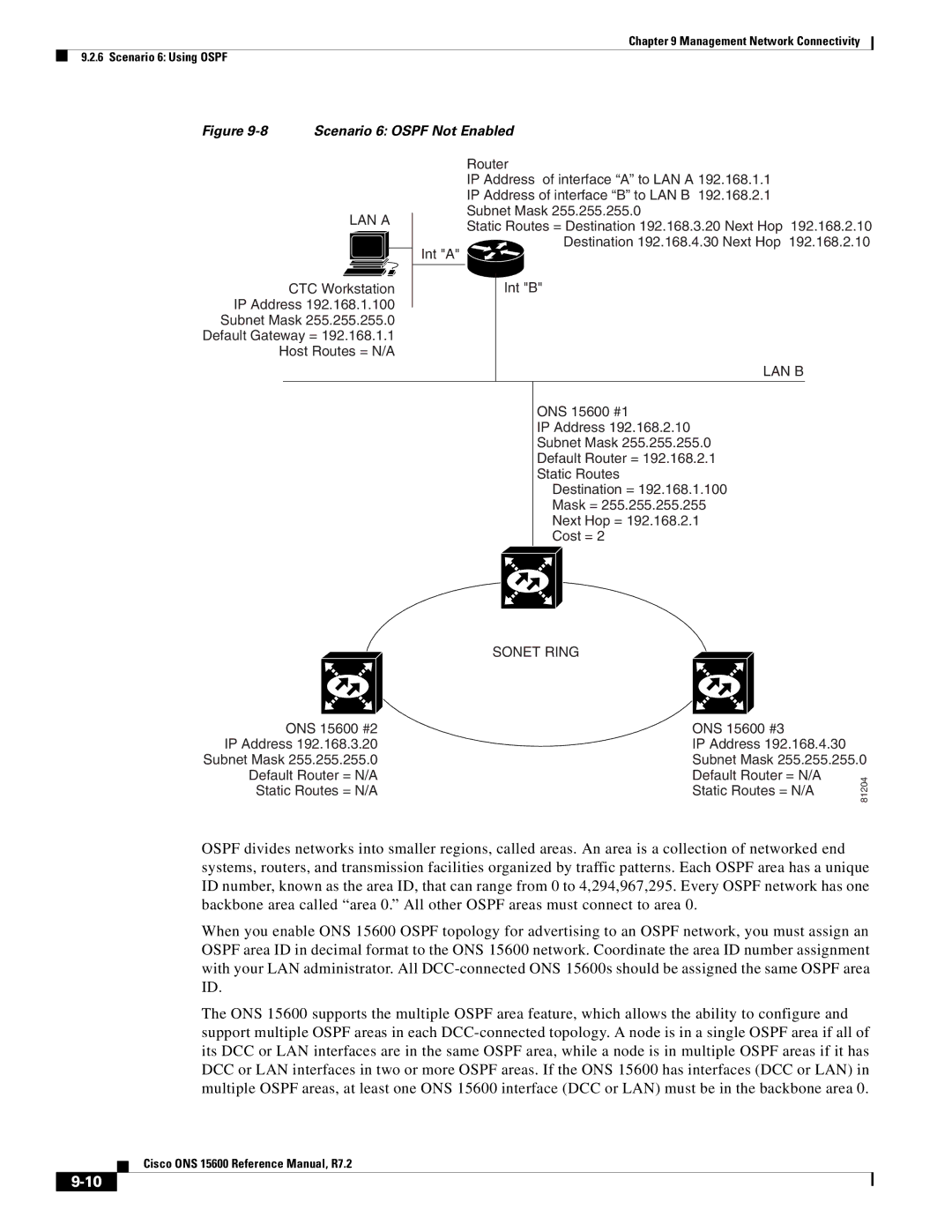
Scenario 6 Ospf Not Enabled
Scenario 7 Provisioning the ONS 15600 Proxy Server
Firewall Not Enabled
Proxy Server Gateway Settings
ENE
Setting ONS 15600 GNE ONS 15600 ENE
GNE
Ospf LAN
81209
Firewall Enabled
Packets Arriving At Accepts Rejects
Scenario 8 Dual GNEs on a Subnet
13 Nodes Behind a Firewall
15 Scenario 8 Dual GNEs on the Same Subnet
Provisionable Patchcords
16shows a network with dual GNEs on different subnets
TXPPMR2.5G
Routing Table
MXP2.5G10G MXP2.5G10E
OC-192
6shows sample routing entries for an ONS
Entry Destination Mask Gateway Interface
FTP
External Firewalls
Port Function Action
Http
TL1
3082 Raw TL1 3083
Open GNE
Management Network Connectivity Open GNE
18 Proxy and Firewall Tunnels for Foreign Terminations
TCP/IP and OSI Networking
19 Foreign Node Connection to an ENE Ethernet Port
Point-to-Point Protocol
OSI Model IP Protocols OSI Protocols IP-OSI Mediation
Link Access Protocol on the D Channel
OSI Connectionless Network Service
Field Definition Description
SEL
OSI Routing
End System-to-Intermediate System Protocol
Intermediate System-to-Intermediate System
Tarp
Field Abbreviation Size bytes Description
PDU
Type Description Procedure
Tarp Processing
Process General Tarp Flow
Default Range Timer Description Seconds
Tarp Loop Detection Buffer
Manual TID to Nsap Provisioning
6 TCP/IP and OSI Mediation
Manual Tarp Adjacencies
OSI Virtual Routers
TD Protocol Flow
FT-TD
Routing Mode Router Router 2 Per area Per is
IP-over-CLNS Tunnels
Is L1/L2
Provisioning IP-over-CLNS Tunnels
25 IP-over-CLNS Tunnel Flow
IP-Over-CLNS Tunnel Scenario 1 ONS Node to Other Vendor GNE
Step Purpose
IP-Over-CLNS Tunnel Scenario 2 ONS Node to Router
CTC
IP Over Clns Tunnel Scenario 2 ONS Node to Router
Management Network Connectivity IP-over-CLNS Tunnels
9 OSI/IP Networking Scenarios
CTC/CTM IP DCN ONS GNE
CTC/CTM IP OSS IP DCN ONS GNE
OSI GNE
CTC/CTM IP OSS
9.4 OSI/IP Scenario 4 Multiple ONS DCC Areas
9.5 OSI/IP Scenario 5 GNE Without an OSI DCC Connection
33 OSI/IP Scenario 4 Multiple ONS DCC Areas
34 OSI/IP Scenario 5 GNE Without an OSI DCC Connection
OSI/IP Scenario 7 -36 shows an example of a European network
ONS NE
Cisco ONS 15600 Reference Manual, R7.2
OSI/LAP-D
OSI Provisioning in CTC
Tab Actions
10-1
Any Service Any Port Card Application
GE LX
10-2
Transport Functionality
GFP
10-3
ONS 15600 Ethernet Frame Transport
Encapsulations
Ethernet Rates and Mapping
Frame Size
Path and Circuit Sizes
Bridge Control Protocol
Protocols over Ethernet
Oversubscription
PPP Half Bridge
10-6
Buffering and Flow Control
Vlan
Autonegotiation
10-7
Gigabit EtherChannel/IEEE 802.3ad Link Aggregation
10-8
Alarms, Conditions, and History
11-1
Column Information Recorded
1describes in the information in the Alarms window
Description Description of the alarm
11-2
Color Description
11-3
MON Object Optical Syntax and Examples
Alarm Window
Alarm-Affected Circuits
Button Action
Conditions Window
11-5
Button
Conditions Window Actions
5shows the actions you can perform in the Conditions window
Retrieve Filter
11-7
History Window
Description Description of the condition
7describes the information in the History window
11-8
Alarm Profile Window
Alarm Profiles
Alarm History Actions
11-9
11-10
Alarm Profile Buttons
Button Description
Alarm Profile Applications
Alarm Profile Editing
Alarm Severity Option
Row Display Options
11-12
Alarm Filter
Alarm Suppression
Alarms Suppressed by User Command
External Alarms and Controls
Alarms Suppressed for Maintenance
11-13
External Control Output
External Alarm Input
Virtual Wires for External Alarms in Mixed Networks
11-14
Virtual Wires Seen from an ONS
11-15
11-16
Threshold Performance Monitoring
12-1
12-2
Intermediate-Path Performance Monitoring
Line Terminating Equipment
2shows the Provisioning Sonet STS tabs for an OC-48 card
12-3
Pointer Justification Count
12-4
12-5
Performance-Monitoring Parameter Definitions
Parameter Definition
12-6
12-7
12-8
Optical Card Performance Monitoring
12-9
Line FE Optics NE 3 STS Path FE
3lists the near-end and far-end section layer PMs
Section NE Line NE
PSC 1+1
Asap Card Optical Performance Monitoring Parameters
Asap Card Performance Monitoring
Physical Layer Parameters
STS SES-P
Parameter Meaning
Asap Card Ethernet Performance Monitoring Parameters
Asap Card Ether Port Statistics Window
12-12
12-13
12-14
Asap Card Ether Ports Utilization Window
12-15
MaxBaseRate
Asap Card Ether Ports History Window
Asap Card POS Ports Statistics Parameters
Time Interval Number of Intervals Displayed
12-17
Asap Card POS Ports Utilization Window
Asap Card POS Ports History Window
12-18
Snmp Overview
13-1
Basic Snmp Components
13-2
13-3
Example of the Primary Snmp Components
Snmp Message Types
Snmp External Interface Requirement
Snmp Version Support
Operation Description
This section contains the following information
Snmp Management Information Bases
IETF-Standard MIBs for ONS
Number Module Name Title/Comments
HC-RMON-MIB
Snmp Trap Content
Proprietary ONS 15600 MIBs
13-6
13-7
Generic and Ietf Traps
Variable Trap Bindings
13-8
EntConfigChange from RFC AuthenticationFailure From RFC
RFC
13-9
13-10
Proxy Over Firewalls
13-11
HC-RMON-MIB Support
Remote Monitoring
13.8.2 64-Bit Rmon Monitoring over DCC
Row Creation in MediaIndependentTable
Ethernet Statistics Rmon Group
History Control Rmon Group
Row Deletion in historyControl Table
Alarm Rmon Group
Row Creation in historyControlTable
Ethernet History Rmon Group
Event Rmon Group
Alarm Table
Row Deletion in alarmTable
Event Table
13-16
Slot Assignments
Shelf Specifications
Bandwidth
Cards
Configurations
Dimensions
Cisco Transport Controller
8 TL1 Craft Interface
Alarm Interface
External LAN Interface
Modem Interface
Database Storage
Environmental Specifications
Power Specifications
Card Type Card Name Watts
Table A-3shows the TSC card specifications
Card Specifications
TSC Card Specifications
Specification Type Description
Table A-4shows the Ssxc card specifications
Ssxc Specifications
3 OC48/STM16 LR/LH 16 Port 1550 Specifications
Specification Type Description
4 OC48/STM16 SR/SH 16 Port 1310 Specifications
5 OC192/STM64 LR/LH 4 Port 1550 Specifications
OGI
6 OC192/STM64 SR/SH 4 Port 1310 Specifications
Asap Specifications
Table A-9shows the Asap card specifications
Transmitter Output Receiver Input Power
SFP/XFP Specifications
Filler Card Specifications
Min/Max dBm
Table A-13lists the available Dwdm SFPs
Interface Wavelength
PRBS23
Wavelength Fiber Type Cable Distance
OOS-AU
Service States
State Qualifier Definition
OOS-AUMA
Administrative States
Secondary State Definition
Current Service State Action Next Service State
Service State Transitions
Card Service State Transitions
OOS-AUMA,MT & UEQ
OOS-AU,MEA
OOS-AU,MEA & MT
OOS-AUMA,MT & Swdl
Port and Cross-Connect Service State Transitions
OOS-MA,LPBK & MT
OOS-AU,AINS & FLT
OOS-AUMA,FLT & Lpbk
OOS,DSBLD Put the port or cross-connect
Loopback Alarm/condition is raised
OOS,MT
Page
Network Element Defaults
Network Element Defaults Description
Card Default Settings
Configuration Defaults
3.1 OC1924 Card Default Settings
Threshold Defaults
Defaults by Card
Default Name Default Value Default Domain
OPT-LOW, OPT-LOW + 1, OPT-LOW
LBC-LOW, LBC-LOW + 1, LBC-LOW
OPR-LOW, OPR-LOW + 1, OPR-LOW
Default Name Default Value Default Domain
Default Name Default Value Default Domain
Default Name Default Value Default Domain
OPR-LOW, OPR-LOW +
3.2 OC4816 Card Default Settings
LBC-LOW, LBC-LOW +
OPT-LOW, OPT-LOW +
Default Name Default Value Default Domain
Default Name Default Value Default Domain
Default Name Default Value Default Domain
IS,AINS IS, OOS,DSBLD, OOS,MT
Asap Card Default Settings
OOS,DSBLD IS, OOS,DSBLD, OOS,MT IS,AINS
ASAP4.config.oc192.sts.IPPMEnabled
ASAP4.config.oc192.line.State
ASAP4.config.oc192.line.SyncMsgIn
ASAP4.config.oc3.line.SyncMsgIn
ASAP4.physicalthresholds.oc12.warning.1day.LBC-HIGH 200 %
ASAP4.physicalthresholds.oc3.alarm.OPR-HIGH 200 %
ASAP4.physicalthresholds.oc48.warning.15min.OPT-HIGH 120 %
Default Name Default Value Default Domain
Default Name Default Value Default Domain
Default Name Default Value Default Domain
Default Name Default Value Default Domain
Default Name Default Value Default Domain
Default Name Default Value Default Domain
Default Name Default Value Default Domain
Default Name Default Value Default Domain
Default Name Default Value Default Domain
Default Name Default Value Default Domain
Default Name Default Value Default Domain
Default Name Default Value Default Domain
Node Default Settings
IS,AINS OOS,DSBLD OOS,MT
Default Default Name Value Domain
NODE.circuits.State
False True
True False
NODE.network.general.AlarmMissingBackplaneLAN
NODE.general.UseDST
ProxyOnlyNo
NODE.osi.tarp.LDB
NODE.osi.tarp.L2DataCache
NODE.osi.tarp.LANStormSuppression
NODE.osi.tarp.PDUsL2Propagation
NODE.protection.blsr.SpanRevertive
NODE.security.passwordAging.EnforcePasswordAging
B8ZS B8ZS, AMI
ESF ESF, D4
RES=DUS
Tncress
ST3EREST
NODE.timing.general.SSMMessageSet Generation
Time Zones
NODE.timing.general.Revertive
GMT
GMT Greenwich Mean Time
CTC Default Settings
Default Default Name Value Default Domain
True TRUE, False
IN-1
Bits
IN-2
IN-3
Corba
CTC
Dhcp
DCC
DCN
Dwdm
IN-5
Iiop
IN-6
IN-7
JRE
LAN
Nsap
Viewing popup information NPJC-Pdet parameter
NPJC-Pgen parameter
IN-8
Cable breakout
Power requirements Timing
PM read points
Radius
Sntp
PIM
LAP-D OSI
SSM
IN-11
PST B-1 Pstq B-1
Rmon
IN-12
Sonet
SSM SST
TCA
IN-13
IN-14