Clarity - INT9 A/D converter | Installation |
2.3.2Connection of starting cables:
Starting input reacts to a change of the TTL logical level (5V) or to a connection by any contact (button, contact of relay).
The input implicitly reacts to a change from HIGH to LOW (or closing of a contact). The input function may be altered by changing the Down option to Up in the External Start/Stop section of the Method Setup - Measurement dialog (accessible from the Instrument window using the - Method - Measurement command).
Note: For schemes and hints describing the typical autosampler wirings see the Device setup and wiring chapter of the Getting Started Manual.
2.4Clarity configuration 
1.Start the Clarity station by clicking on the ![]() icon on the desktop.
icon on the desktop.
2.Invoke the System Configuration dialog using the System – Configuration command.
3.Press the Add button (see Fig. 4) to invoke the Available Control Modules dialog.
4.Select the DataApex INT9 A/D Card and press
the Add button.
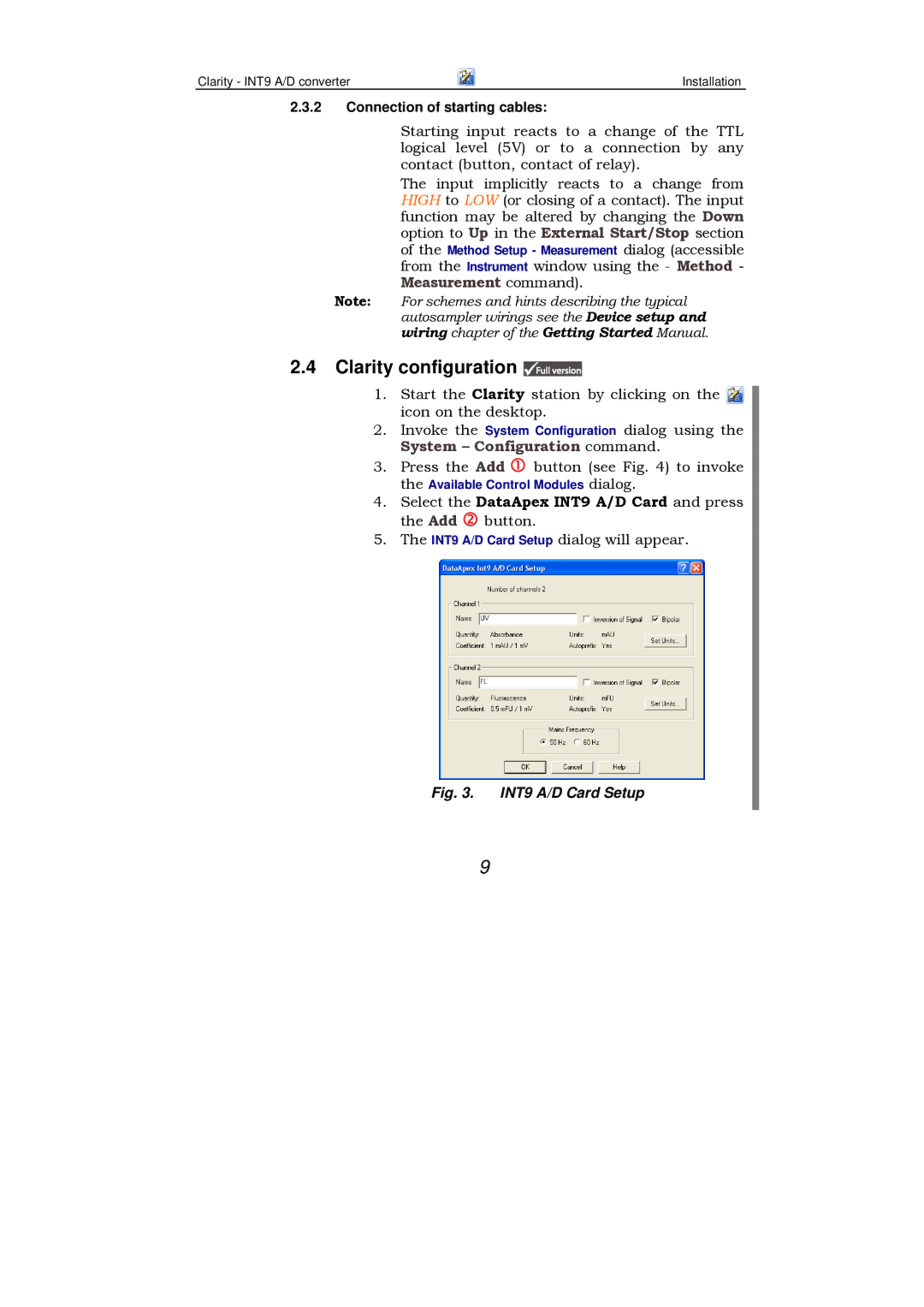
5. The INT9 A/D Card Setup dialog will appear.
Fig. 3. INT9 A/D Card Setup
9