Step 3
Step 4
Important!
Connect all source components to the SSP rear panel.
Source devices that you may want to integrate into your surround system might include audio and video devices, such as CD and DVD players, and your main display, such as a
Make sure you keep a detailed record of the rear panel connectors that you used while connecting the source components!
To help keep track of the different sources, we recommend keeping a pencil-
NOTE: In the SSP default settings, each rear panel input is associated with an input selection within the Setup menu. A complete list of the factory default input settings is available at the end of this manual.
Connect the power amplifiers to the SSP rear panel.
Verify that the power amplifier(s) is plugged in but powered OFF before connecting to the SSP!
We recommend using high quality cables with XLR connectors. Connect the cables to the Main Analog Audio outputs on the SSP rear panel, using the balanced XLR connection options.
NOTE: These pin assignments are consistent with the standards adopted by the Audio Engineering Society. Refer to the operating manuals of your
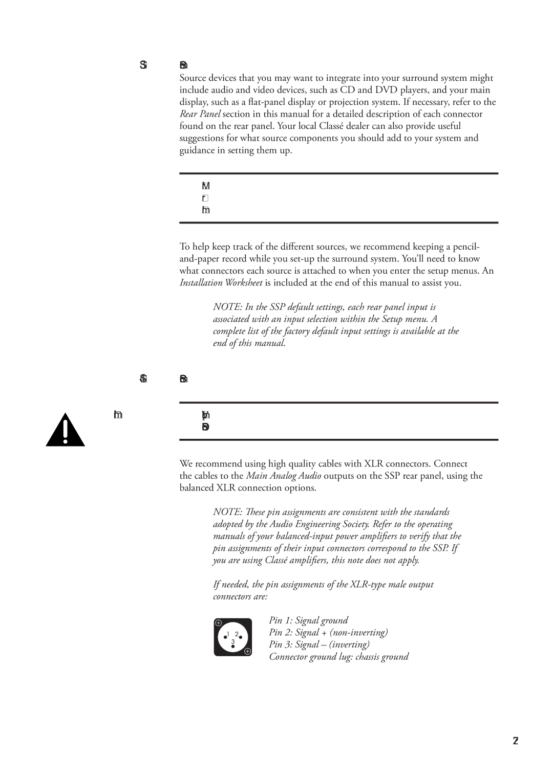
If needed, the pin assignments of the
Pin 1: Signal ground
Pin 2: Signal +
Pin 3: Signal – (inverting)
Connector ground lug: chassis ground
27