Introduction ~ Controls and Connections
C.LED Meter. The LED bar meter is displays the audio level of any selected input or output on the AP400, as well as displaying echo return loss (ERL) and echo return loss enhancement (ERLE) for mic channels
D.Meter. The Meter button takes you directly to the Meter branch of the AP400’s LCD programming tree.
E.System, Inputs, Outputs, Routing. These buttons provide direct access to the corresponding sections in the LCD menu.
F.Mic On LED. These LEDs indicate microphone gate status.
G.On. The On button connects and adapts the AP400 to the telephone line. Pressing and holding the On button for more than two seconds while the AP400 is active readapts the unit.
H.Off. The Off button disconnects the AP400 from the telephone line and mutes all audio to and from the telephone line.
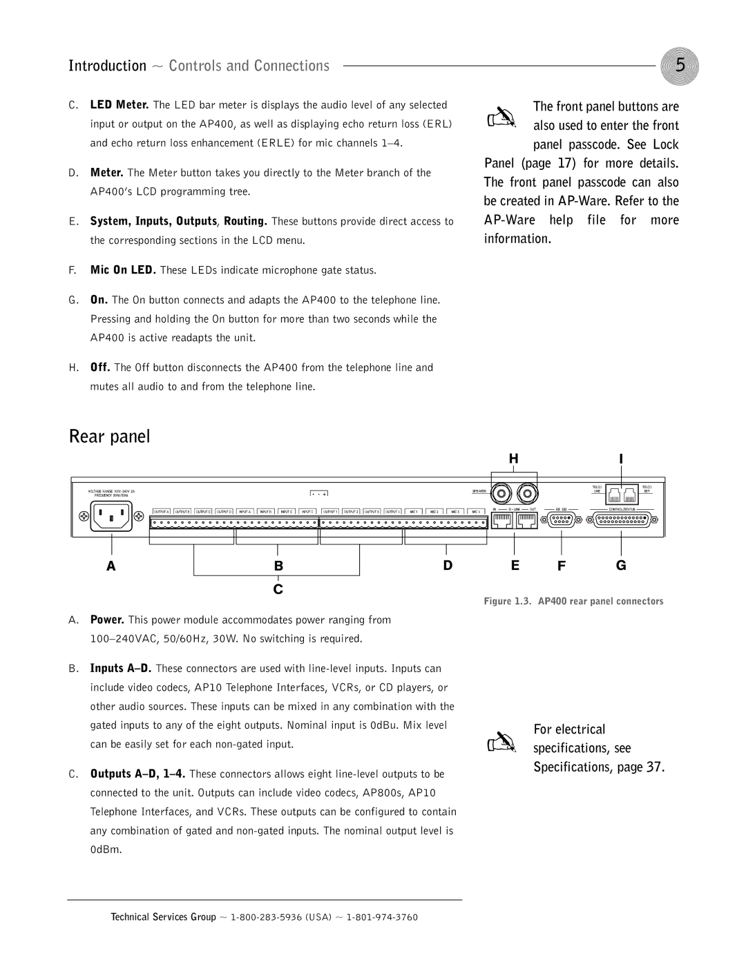
Rear panel
5
✍ The front panel buttons are also used to enter the front panel passcode. See Lock
Panel (page 17) for more details. The front panel passcode can also be created in
HI
|
|
|
|
|
| D |
A |
| B |
| |||
C
A.Power. This power module accommodates power ranging from
B.Inputs
C.Outputs
E F G
Figure 1.3. AP400 rear panel connectors
For electrical ✍ specifications, see
Specifications, page 37.
Technical Services Group ~