
KGL-40, KGL-60, KGL-80, KGL-100, KGL-40-T, KGL-60-T, KGL-80-T, KGL-40-SH, KGL-60-SH, KGL-40-TSH, KGL-100, KGL-40-T, KGL-40-TSH, KGL-40, KGL-40-T, KGL-40SH, KGL-80-T, KGL-40-SH specifications
Cleveland Range has established itself as a leading manufacturer of high-quality commercial kitchen equipment, particularly known for its diverse range of steamers. Among their notable offerings are the Cleveland Range KGL series models including KGL-80-T, KGL-40-SH, KGL-40-TSH, KGL-40, KGL-40-T, KGL-40SH, KGL-100, KGL-60, KGL-80, and KGL-60-T. These models are specifically designed to meet the needs of busy commercial kitchens, providing efficiency, durability, and precision in cooking.The KGL-80-T model stands out with its generous cooking capacity, making it ideal for large-scale food preparation. It is equipped with advanced controls that allow for easy monitoring of cooking times and temperatures, ensuring that food is cooked evenly and to perfection. The integrated steaming technology maintains high levels of moisture, preserving the flavor and nutritional value of the food.
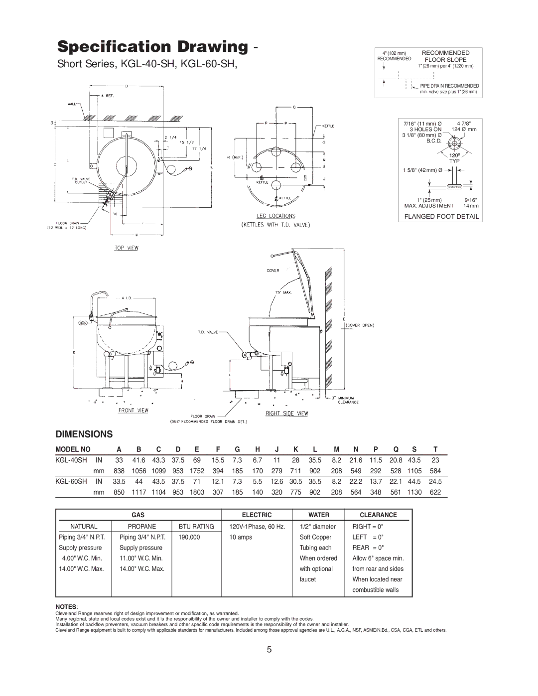
The KGL-40-SH and KGL-40-TSH models are tailored for mid-sized operations but still offer robust performance. These steamers incorporate user-friendly digital controls that facilitate hassle-free operation. The stainless-steel construction ensures durability and ease of cleaning, essential for maintaining hygiene in a busy kitchen environment.
Cleveland's KGL-40-T and KGL-40SH versions feature energy-efficient options, significantly reducing water and energy consumption without compromising on cooking quality. These models utilize a sophisticated water level management system that minimizes operational costs while maximizing cooking efficiency.
For establishments requiring even larger capacities, the KGL-100 model is an ideal solution, designed to cater to extensive foodservice operations. It boasts advanced steam generation technology, allowing for rapid heating and cooking. The ability to stack multiple trays enhances its functionality, making it a powerful tool for large events or high-demand services.
The KGL-60 and KGL-60-T models blend functionality with advanced features. The digital control panel provides precise steam control, time management, and temperature settings. Users can easily program multiple recipes, making it convenient to switch between different dishes quickly.
In summary, Cleveland Range's KGL series, including the KGL-80-T, KGL-40-SH, KGL-40-TSH, KGL-40, KGL-40-T, KGL-40SH, KGL-100, KGL-60, KGL-80, KGL-60-T, and others, epitomize excellence in commercial kitchen technology. With their commitment to quality, durability, and energy efficiency, these steamers are designed to enhance the culinary capabilities of any kitchen, ensuring that chefs can deliver exceptional meals consistently. Each model in the KGL series is tailored to meet the diverse needs of foodservice operations, from small restaurants to large catering businesses, ensuring optimal performance and reliability.