1-10RAID Array 3000 Pedestal Storage Subsystem Hardware User’s Guide
UltraSCSI Buses
The pedestal contains two, 16-bit, single-ended, wide UltraSCSI buses (factory-configured as a split bus) that connects the controllers to the disk drives.
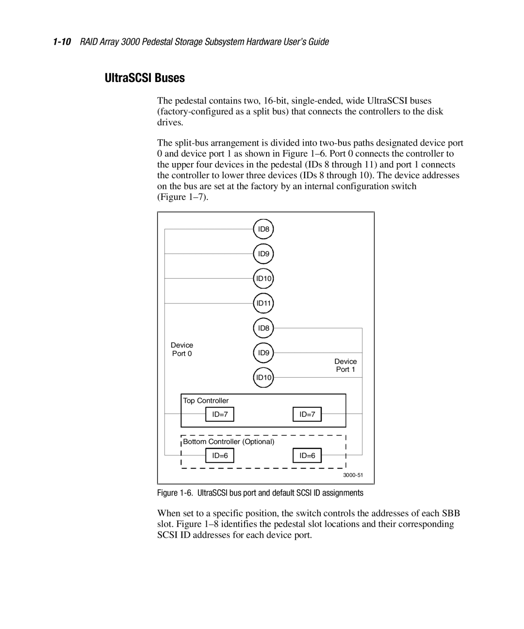
The split-bus arrangement is divided into two-bus paths designated device port 0 and device port 1 as shown in Figure 1–6. Port 0 connects the controller to the upper four devices in the pedestal (IDs 8 through 11) and port 1 connects the controller to lower three devices (IDs 8 through 10). The device addresses on the bus are set at the factory by an internal configuration switch
(Figure 1–7).
| ID8 |
| ID9 |
| ID10 |
| ID11 |
| ID8 |
Device | ID9 |
Port 0 |
| Device |
| Port 1 |
| ID10 |
Top Controller | |
ID=7 | ID=7 |
Bottom Controller (Optional) |
ID=6 | ID=6 |
| 3000-51 |
Figure 1-6. UltraSCSI bus port and default SCSI ID assignments
When set to a specific position, the switch controls the addresses of each SBB slot. Figure 1–8 identifies the pedestal slot locations and their corresponding SCSI ID addresses for each device port.