vi RAID Array 3000 Pedestal Storage Subsystem Hardware User's Guide |
| |
Figure | ||
Figure | ||
Figure | ||
Figure | ||
Figure | ||
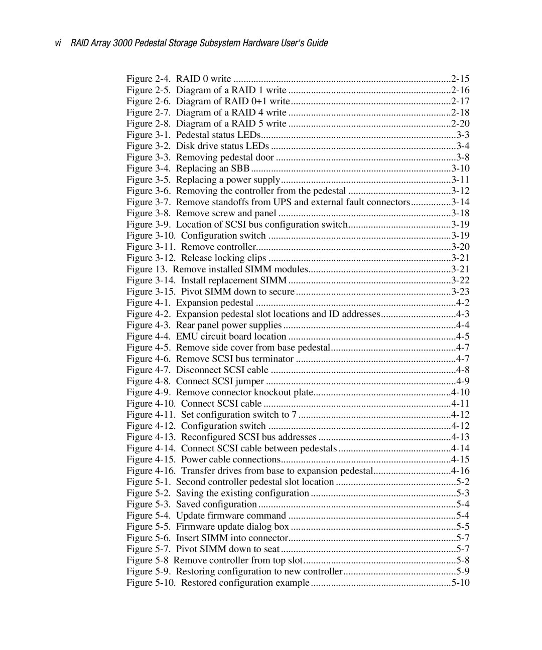
Figure | Pedestal status LEDs | |
Figure | Disk drive status LEDs | |
Figure | Removing pedestal door | |
Figure | ||
Figure | Replacing a power supply | |
Figure | Removing the controller from the pedestal | |
Figure | Remove standoffs from UPS and external fault connectors | |
Figure | ||
Figure | Location of SCSI bus configuration switch | |
Figure | Configuration switch | |
Figure | Remove controller | |
Figure | Release locking clips | |
Figure 13. Remove installed SIMM modules | ||
Figure | Install replacement SIMM | |
Figure | ||
Figure | Expansion pedestal | |
Figure | Expansion pedestal slot locations and ID addresses | |
Figure | Rear panel power supplies | |
Figure | EMU circuit board location | |
Figure | Remove side cover from base pedestal | |
Figure | ||
Figure | Disconnect SCSI cable | |
Figure | ||
Figure | Remove connector knockout plate | |
Figure | Connect SCSI cable | |
Figure | Set configuration switch to 7 | |
Figure | Configuration switch | |
Figure | Reconfigured SCSI bus addresses | |
Figure | Connect SCSI cable between pedestals | |
Figure | Power cable connections | |
Figure | Transfer drives from base to expansion pedestal | |
Figure | Second controller pedestal slot location | |
Figure | Saving the existing configuration | |
Figure | Saved configuration | |
Figure | ||
Figure | Firmware update dialog box | |
Figure | Insert SIMM into connector | |
Figure | ||
Figure | ||
Figure | Restoring configuration to new controller | |
Figure | Restored configuration example | |
Page 6
Image 6
