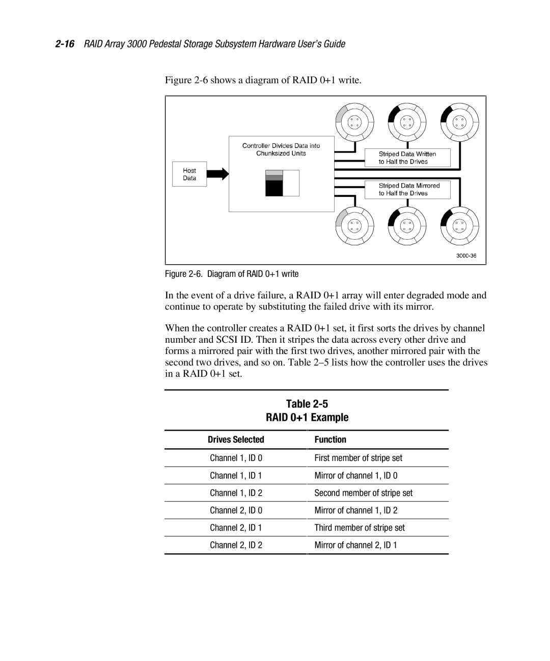
Figure 2-6 shows a diagram of RAID 0+1 write.
Figure 2-6. Diagram of RAID 0+1 write
In the event of a drive failure, a RAID 0+1 array will enter degraded mode and continue to operate by substituting the failed drive with its mirror.
When the controller creates a RAID 0+1 set, it first sorts the drives by channel number and SCSI ID. Then it stripes the data across every other drive and forms a mirrored pair with the first two drives, another mirrored pair with the second two drives, and so on. Table
Table
RAID 0+1 Example
Drives Selected
Channel 1, ID 0
Channel 1, ID 1
Channel 1, ID 2
Channel 2, ID 0
Channel 2, ID 1
Channel 2, ID 2
Function
First member of stripe set
Mirror of channel 1, ID 0
Second member of stripe set
Mirror of channel 1, ID 2
Third member of stripe set
Mirror of channel 2, ID 1