RAID Array Controller
Table
Controller Specifications continued
Item |
| Specifications |
Environmental
Temperature
Relative humidity
Physical size
Power requirements
41ºF to 122ºF (5ºC to 50ºC) operating,
10% to 95%
8.55in (21.7 cm) deep, 5.03 in wide, 1.6 in (4 cm) high
5 VDC @ 3 A, peak; - 12 VDC @ 1 A, peak
Controller Reset and LED Indicators
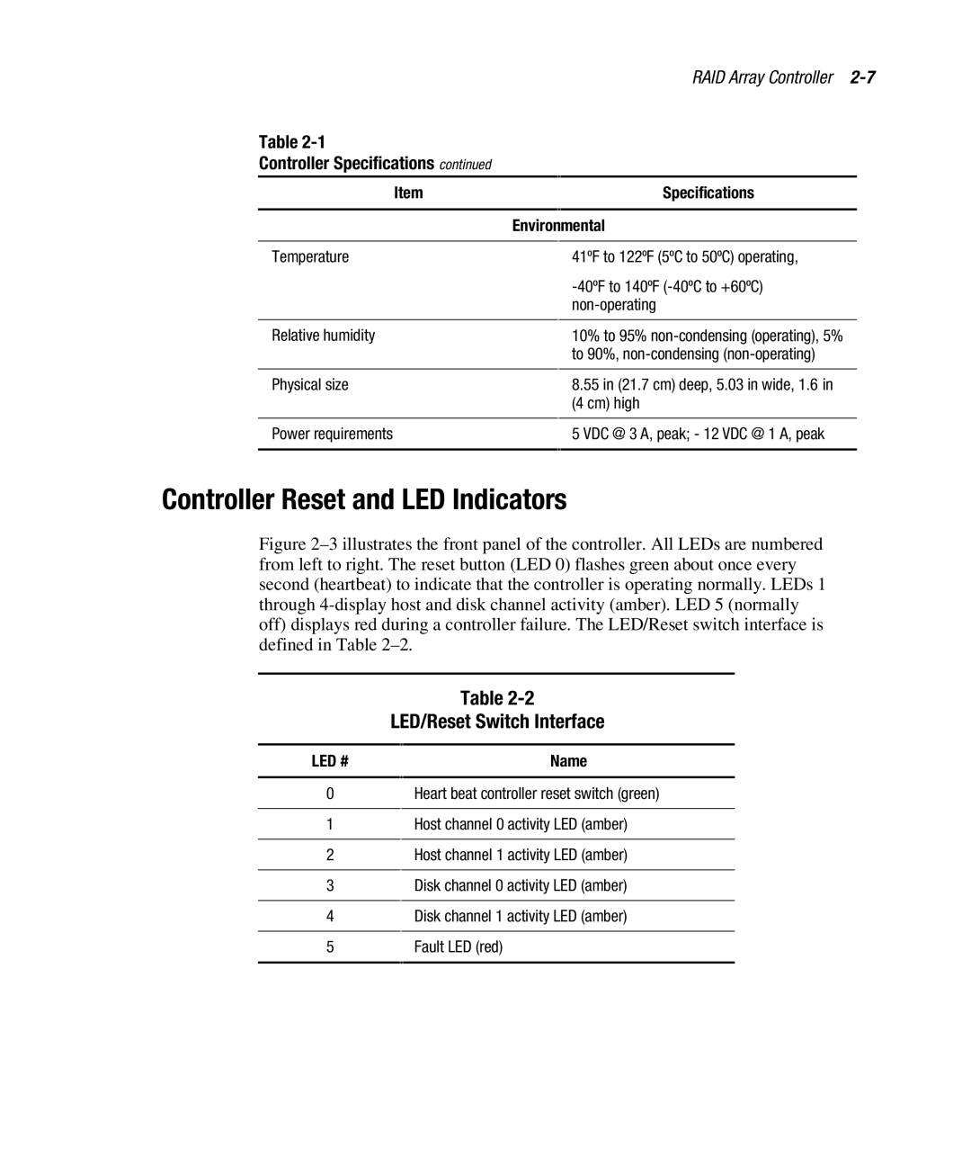
Figure 2–3 illustrates the front panel of the controller. All LEDs are numbered from left to right. The reset button (LED 0) flashes green about once every second (heartbeat) to indicate that the controller is operating normally. LEDs 1 through 4-display host and disk channel activity (amber). LED 5 (normally off) displays red during a controller failure. The LED/Reset switch interface is defined in Table 2–2.
Table
LED/Reset Switch Interface
LED #
0
1
2
3
4
5
Name
Heart beat controller reset switch (green)
Host channel 0 activity LED (amber)
Host channel 1 activity LED (amber)
Disk channel 0 activity LED (amber)
Disk channel 1 activity LED (amber)
Fault LED (red)
