Introduction to the Compaq FTAM Responder | The Responder and Underlying Subsystems |
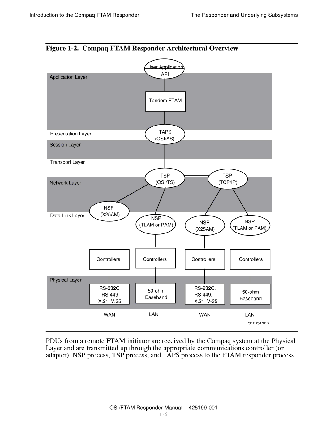
Figure 1-2. Compaq FTAM Responder Architectural Overview
| User Application | |
Application Layer | API | |
|
| |
|
| |
|
|
|
| Tandem FTAM | |
|
|
|
|
|
|
Presentation Layer |
|
|
|
| TAPS |
|
|
|
|
|
|
|
| |
|
|
|
|
| (OSI/AS) |
|
|
|
|
|
|
|
| |
Session Layer |
|
|
|
|
|
|
|
|
|
|
|
|
| |
|
|
|
|
|
|
|
|
|
|
|
|
|
|
|
Transport Layer |
|
|
|
|
|
|
|
|
|
|
|
|
| |
|
|
|
|
|
| TSP |
|
|
| TSP | ||||
Network Layer |
|
|
|
| (OSI/TS) |
|
|
| (TCP/IP) | |||||
|
| NSP |
|
|
|
|
|
|
|
|
|
|
| |
Data Link Layer | (X25AM) |
| NSP |
|
|
|
|
| NSP | |||||
|
|
|
|
|
| NSP |
|
| ||||||
|
|
|
|
| (TLAM or PAM) |
|
|
| ||||||
|
|
|
|
|
| (X25AM) |
|
| (TLAM or PAM) | |||||
|
|
|
|
|
|
|
|
|
| |||||
|
|
|
|
|
|
|
|
|
|
|
|
|
|
|
|
|
|
|
|
|
|
|
|
|
|
|
|
|
|
|
|
|
|
|
|
|
|
|
|
|
|
|
|
|
|
| Controllers |
| Controllers |
| Controllers |
|
| Controllers |
| ||||
|
|
|
|
|
|
|
|
|
|
|
|
|
|
|
|
|
|
|
|
|
|
|
|
|
|
|
|
|
|
Physical Layer |
|
|
|
|
|
|
|
|
|
|
|
|
| |
|
|
|
|
|
|
| ||||||||
|
|
|
|
|
|
| ||||||||
|
|
| Baseband |
|
|
| Baseband |
| ||||||
|
| X.21, V.35 |
|
| X.21, |
|
|
| ||||||
|
|
|
|
|
|
|
|
|
|
| ||||
|
|
|
|
|
|
|
|
|
|
|
|
|
|
|
|
| WAN |
| LAN |
| WAN |
|
| LAN | |||||
CDT 204.CDD
PDUs from a remote FTAM initiator are received by the Compaq system at the Physical Layer and are transmitted up through the appropriate communications controller (or adapter), NSP process, TSP process, and TAPS process to the FTAM responder process.
