Crestron Residential Lighting Design Guide | GreenLight |
Module Installation
In accordance with all national and local codes a licensed electrician, , must mount the terminal blocks and modules in
Terminal blocks are installed along the left side of single- wide enclosures and along the outside edges (left and right sides) of doublewide enclosures. Modules are installed along the right side of singlewide enclosures and
Refer to the illustrations when considering the location of terminal blocks and modules within an enclosure.
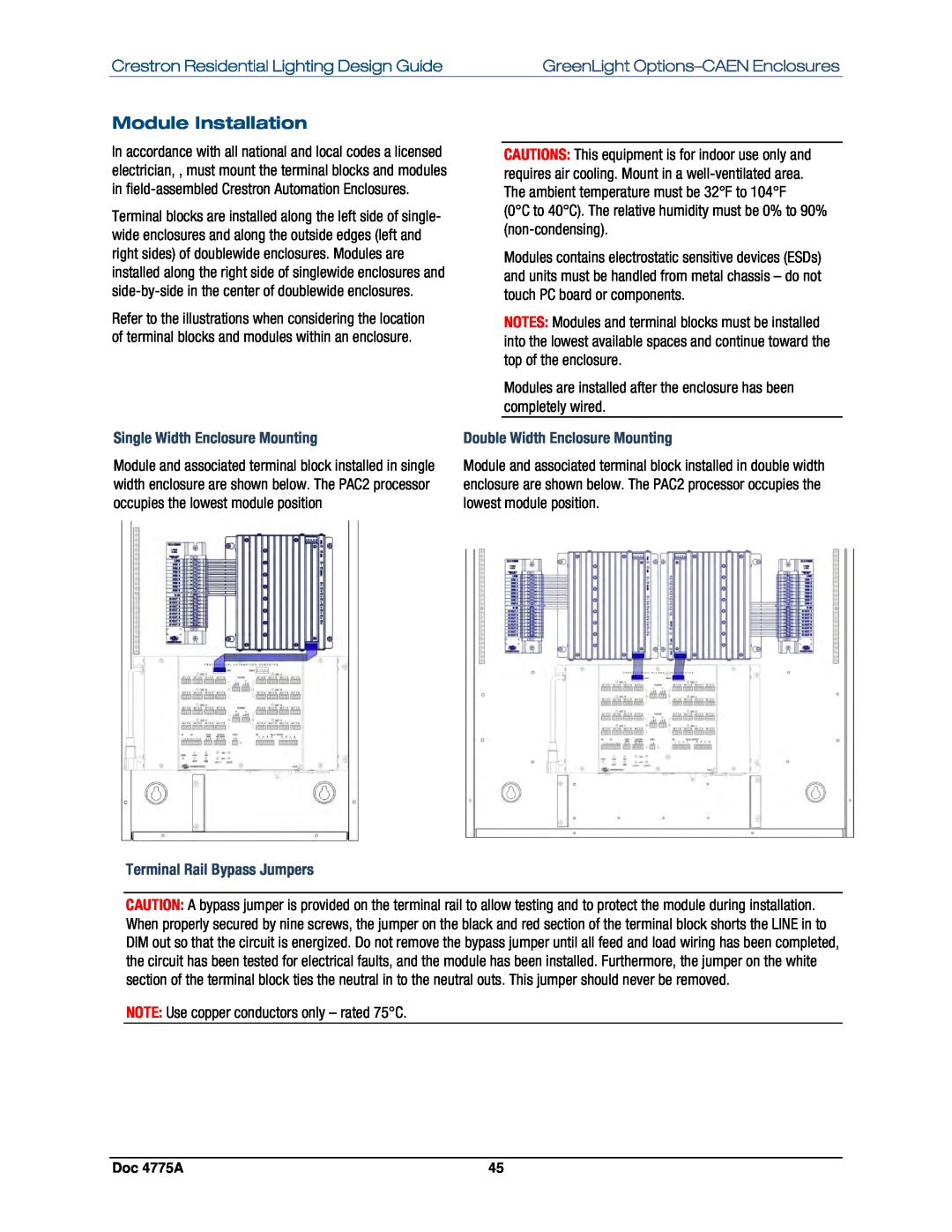
Single Width Enclosure Mounting
Module and associated terminal block installed in single width enclosure are shown below. The PAC2 processor occupies the lowest module position
CAUTIONS: This equipment is for indoor use only and requires air cooling. Mount in a
Modules contains electrostatic sensitive devices (ESDs) and units must be handled from metal chassis – do not touch PC board or components.
NOTES: Modules and terminal blocks must be installed into the lowest available spaces and continue toward the top of the enclosure.
Modules are installed after the enclosure has been completely wired.
Double Width Enclosure Mounting
Module and associated terminal block installed in double width enclosure are shown below. The PAC2 processor occupies the lowest module position.
Terminal Rail Bypass Jumpers
CAUTION: A bypass jumper is provided on the terminal rail to allow testing and to protect the module during installation. When properly secured by nine screws, the jumper on the black and red section of the terminal block shorts the LINE in to DIM out so that the circuit is energized. Do not remove the bypass jumper until all feed and load wiring has been completed, the circuit has been tested for electrical faults, and the module has been installed. Furthermore, the jumper on the white section of the terminal block ties the neutral in to the neutral outs. This jumper should never be removed.
NOTE: Use copper conductors only – rated 75°C.
Doc 4775A | 45 |