CY7C1440AV33
CY7C1442AV33
CY7C1446AV33
TAP AC Switching Characteristics Over the operating Range[10, 11]
Parameter | Description | Min. | Max. | Unit |
Clock |
|
|
|
|
|
|
|
|
|
tTCYC | TCK Clock Cycle Time | 50 |
| ns |
tTF | TCK Clock Frequency |
| 20 | MHz |
tTH | TCK Clock HIGH time | 20 |
| ns |
tTL | TCK Clock LOW time | 20 |
| ns |
Output Times |
|
|
| |
tTDOV | TCK Clock LOW to TDO Valid |
| 10 | ns |
tTDOX | TCK Clock LOW to TDO Invalid | 0 |
| ns |
|
|
|
| |
tTMSS | TMS | 5 |
| ns |
tTDIS | TDI | 5 |
| ns |
tCS | Capture | 5 |
| ns |
Hold Times |
|
|
|
|
|
|
|
|
|
tTMSH | TMS Hold after TCK Clock Rise | 5 |
| ns |
tTDIH | TDI Hold after Clock Rise | 5 |
| ns |
tCH | Capture Hold after Clock Rise | 5 |
| ns |
3.3V TAP AC Test Conditions
Input pulse levels | VSS to 3.3V |
Input rise and fall times | 1ns |
Input timing reference levels | 1.5V |
Output reference levels | 1.5V |
Test load termination supply voltage | 1.5V |
2.5V TAP AC Test Conditions
Input pulse levels | VSS to 2.5V |
Input rise and fall time | 1 ns |
Input timing reference levels | 1.25V |
Output reference levels | 1.25V |
Test load termination supply voltage | ........1.25V |
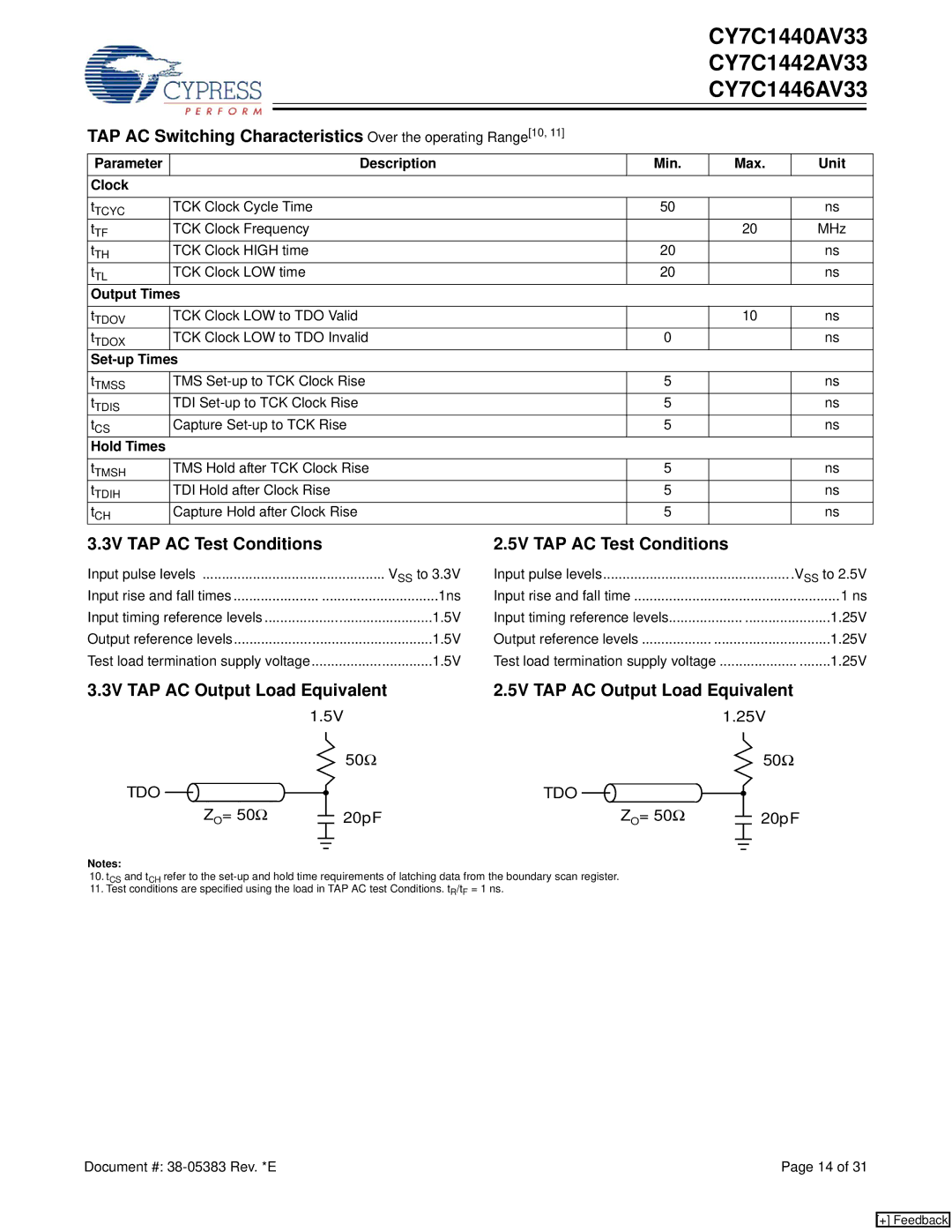
3.3V TAP AC Output Load Equivalent | 2.5V TAP AC Output Load Equivalent | |||||||||||||||||||||||||
|
|
|
|
|
| 1.5V |
|
|
|
|
| 1.25V | ||||||||||||||
|
|
|
|
|
|
|
|
|
|
|
|
| 50Ω |
|
|
|
|
|
|
|
|
|
|
|
| 50Ω |
TDO |
|
|
|
|
|
|
|
|
|
|
|
|
| TDO |
|
|
|
|
|
|
|
|
|
|
|
|
|
|
|
|
|
|
|
|
|
|
|
|
|
|
|
|
|
|
| ||||||||
|
|
|
|
|
|
|
|
|
|
|
|
|
|
|
|
|
|
|
|
|
|
|
| |||
|
|
|
|
|
|
|
|
|
|
|
|
|
|
|
|
|
|
|
|
|
|
|
|
| ||
|
|
|
| ZO= 50Ω |
|
|
|
|
|
|
| 20pF |
|
|
| ZO= 50Ω |
|
|
|
|
|
|
| 20pF | ||
|
|
|
|
|
|
|
|
|
|
|
|
|
|
|
|
|
|
|
|
| ||||||
|
|
|
|
|
|
|
|
|
|
|
|
|
|
|
|
|
|
|
|
|
|
|
|
|
|
|
|
|
|
|
|
|
|
|
|
|
|
|
|
|
|
|
|
|
|
|
|
|
|
|
|
|
|
|
|
|
|
|
|
|
|
|
|
|
|
|
|
|
|
|
|
|
|
|
|
|
|
|
|
|
Notes:
10.tCS and tCH refer to the
11.Test conditions are specified using the load in TAP AC test Conditions. tR/tF = 1 ns.
Document #: | Page 14 of 31 |
[+] Feedback