6 - DIAGNOSTICS - TROUBLESHOOTING

6.1 - General

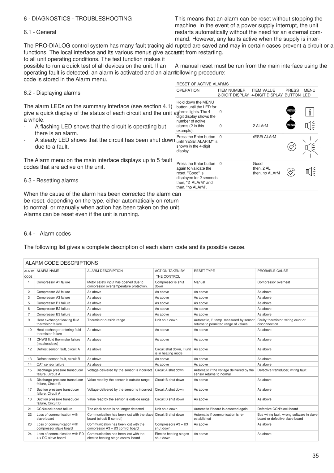
The PRO-DIALOG control system has many fault tracing aid functions. The local interface and its various menus give access to all unit operating conditions. The test function makes it possible to run a quick test of all devices on the unit. If an operating fault is detected, an alarm is activated and an alarm code is stored in the Alarm menu.

6.2 - Displaying alarms

The alarm LEDs on the summary interface (see section 4.1) give a quick display of the status of each circuit and the unit as a whole.

-A flashing LED shows that the circuit is operating but there is an alarm.

-A steady LED shows that the circuit has been shut down due to a fault.

The Alarm menu on the main interface displays up to 5 fault codes that are active on the unit.

6.3 - Resetting alarms

This means that an alarm can be reset without stopping the machine. In the event of a power supply interrupt, the unit restarts automatically without the need for an external com- mand. However, any faults active when the supply is inter- rupted are saved and may in certain cases prevent a circuit or a unit from restarting.

A manual reset must be run from the main interface using the following procedure:

RESET OF ACTIVE ALARMS

OPERATION

ITEM NUMBER

ITEM VALUE

PRESS MENU


2-DIGIT DISPLAY 4-DIGIT DISPLAY BUTTON LED

Hold down the MENU


button until the LED for


alarms lights. The 4-

0


digit display shows the


number of active


alarms (2 in this

0

2 ALArM


example).


Press the Enter button

0

rESEt ALArM


until "rESEt ALARrM" is


shown in the 4-digit


display.


Press the Enter button

0

Good


again to validate the


then, 2 AL


reset. "Good" is


then, no ALArM


displayed for 2 seconds


then, "2 ALArM" and


then, "no ALArM".


When the cause of the alarm has been corrected the alarm can be reset, depending on the type, either automatically on return to normal, or manually when action has been taken on the unit. Alarms can be reset even if the unit is running.

6.4 - Alarm codes

The following list gives a complete description of each alarm code and its possible cause.

ALARM CODE DESCRIPTIONS

ALARM

ALARM NAME

ALARM DESCRIPTION

ACTION TAKEN BY

RESET TYPE

PROBABLE CAUSE

CODE


THE CONTROL


1

Compressor A1 failure

Motor safety input has opened due to

Compressor is shut

Manual

Compressor overheat


compressor overtemperature protection.

down


2

Compressor A2 failure

As above

As above

As above

As above

3

Compressor A3 failure

As above

As above

As above

As above

5

Compressor B1 failure

As above

As above

As above

As above

6

Compressor B2 failure

As above

As above

As above

As above

7

Compressor B3 failure

As above

As above

As above

As above

9

Heat exchanger leaving fluid

Thermistor outside range

Unit shut down

Automatic, if temp. measured by sensor

Faulty thermistor, wiring error or


thermistor failure


returns to permitted range of values

disconnection

10

Heat exchanger entering fluid

As above

As above

As above

As above


thermistor failure


11

CHWS fluid thermistor failure

As above

As above

As above

As above


(master/slave)


12

Defrost sensor fault, circuit A

As above

Circuit shut down, if unit

As above

As above


is in heating mode


13

Defrost sensor fault, circuit B

As above

As above

As above

As above

14

OAT sensor failure

As above

As above

As above

As above

15

Discharge pressure transducer

Voltage delivered by the sensor is incorrect

Circuit A shut down

Automatic if the voltage delivered by the

Defective transducer, wiring fault


failure, Circuit A


sensor returns to normal


16

Discharge pressure transducer

Value read by the sensor is outside range

Circuit B shut down

As above

As above


failure, Circuit B


17

Suction pressure transducer

Voltage delivered by the sensor is incorrect

Circuit A shut down

As above

As above


failure, Circuit A


18

Suction pressure transducer

Value read by the sensor is outside range

Circuit B shut down

As above

As above


failure, Circuit B


21

CCN/clock board failure

The clock board is no longer detected

Unit shut down

Automatic if board is detected again

Defective CCN/clock board

22

Loss of communication with

Communication has been lost with the slave

Circuit B shut down

Automatic if communication is re-

Bus wiring fault, wrong software in slave


slave board

board (circuit B control)


established

board or defective slave board

23

Loss of communication with

Communication has been lost with the

Compressors A3 + B3

As above

As above


compressor slave board

compressor A3 + B3 control board

shut down


24

Loss of communication with PD-

Communication has been lost with the

Electric heating stages

As above

As above


4 x DO slave board

electric heating stage control board

shut down


35

Page 35
Image 35
Carrier 30RY/RYH, 30RA/RH manual Displaying alarms, Resetting alarms, Alarm codes, Then, 2 ALArM Then, no ALArM

30RY/RYH, 30RA/RH specifications

The Carrier 30RY/RYH and 30RA/RH chiller models are leading solutions in commercial and industrial cooling applications. Renowned for their reliability, efficiency, and advanced technologies, these chillers cater to a wide variety of settings, from office buildings to manufacturing facilities.

The 30RY/RYH series features a distinctive design optimized for performance, utilizing a centrifugal compressor that ensures smooth operation under varying loads. One of the standout features of these chillers is their high-efficiency capabilities, which contribute to lower energy consumption. The models are engineered to deliver substantial energy savings, meeting or exceeding the latest ASHRAE and DOE efficiency standards.

A significant aspect of the 30RY and 30RA models is their use of environmentally friendly refrigerants. The 30RYH, for instance, employs R-134a refrigerant, which is designed to minimize ozone depletion while maximizing efficiency. This commitment to sustainability aligns with modern environmental regulations and practices, making these chillers a wise choice for eco-conscious projects.

In terms of control technology, the chiller models come equipped with advanced microprocessor-based controls, providing users with optimal system management and diagnostics. This integrated control system enhances the overall performance and reliability of the chillers, allowing for real-time monitoring and adjustment to ensure peak operational efficiency.

Another key feature is the quiet operation of the 30RY/RYH and 30RA/RH series. Designed with sound attenuation in mind, these units minimize noise pollution, making them suitable for installations in noise-sensitive environments. Additionally, the modular design allows for easy installation and maintenance, reducing downtime and providing flexibility in system design.

Both series also offer robust thermal performance, with the capability to handle a wide range of operating conditions. The chillers excel in terms of cooling capacity, providing solutions for varying thermal loads while maintaining energy efficiency. This adaptability is invaluable for facilities managing seasonal changes in cooling demands.

In summary, the Carrier 30RY/RYH and 30RA/RH chillers represent an ideal blend of efficiency, advanced technology, and eco-friendliness. Their high-performance capabilities, user-friendly controls, and sustainable design make them a top choice for commercial and industrial applications, ensuring dependable cooling solutions for diverse environments.