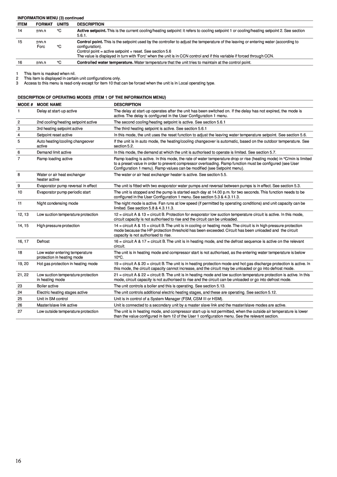
INFORMATION MENU (3) continued
ITEM | FORMAT | UNITS | DESCRIPTION |
14 | ±nn.n | °C | Active setpoint. This is the current cooling/heating setpoint: it refers to cooling setpoint 1 or cooling/heating setpoint 2. See section |
|
|
| 5.6.1. |
15 | ±nn.n |
| Control point. This is the setpoint used by the controller to adjust the temperature of the leaving or entering water (according to |
| Forc | °C | configuration). |
|
|
| Control point = active setpoint + reset. See section 5.6 |
|
|
| The value is displayed in turn with 'Forc' when the unit is in CCN control and if this variable if forced through CCN. |
|
|
|
|
16 | ±nn.n | °C | Controlled water temperature. Water temperature that the unit tries to maintain at the control point. |
|
|
|
|
1This item is masked when nil.
2This item is displayed in certain unit configurations only.
3Access to this menu is
DESCRIPTION OF OPERATING MODES (ITEM 1 OF THE INFORMATION MENU)
MODE # | MODE NAME | DESCRIPTION |
1 | Delay at | The delay at |
|
| active. The delay is configured in the User Configuration 1 menu. |
2 | 2nd cooling/heating setpoint active | The second cooling/heating setpoint is active. See section 5.6.1 |
3 | 3rd heating setpoint active | The third heating setpoint is active. See section 5.6.1 |
4 | Setpoint reset active | In this mode, the unit uses the reset function to adjust the leaving water temperature setpoint. See section 5.6. |
5 | Auto heating/cooling changeover | If the unit is in auto mode, the heating/cooling changeover is automatic, based on the outdoor temperature. See |
| active | section 5.2. |
6 | Demand limit active | In this mode, the demand at which the unit is authorised to operate is limited. See section 5.7. |
|
|
|
7 | Ramp loading active | Ramp loading is active. In this mode, the rate of water temperature drop or rise (heating mode) in °C/min is limited |
|
| to a preset value in order to prevent compressor overloading. Ramp function must be configured (see User |
|
| Configuration 1 menu). Ramp values can be modified (see Setpoint menu). |
|
|
|
8 | Water or air heat exchanger | The water or air heat exchanger heater is active. See section 5.5. |
| heater active |
|
9 | Evaporator pump reversal in effect | The unit is fitted with two evaporator water pumps and reversal between pumps is in effect. See section 5.3. |
10 | Evaporator pump periodic start | The unit is stopped and the pump is started each day at 14.00 p.m. for two seconds. This function needs to be |
|
| configured in the User Configuration 1 menu. See section 5.3 & 4.3.11.3. |
11 | Night condensing mode | The night mode is active. Fan runs at low speed (if permitted by operating conditions) and unit capacity can be |
|
| limited. See section 5.8 & 4.3.11.3. |
12, 13 | Low suction temperature protection | 12 = circuit A & 13 = circuit B. Protection for evaporator low suction temperature circuit is active. In this mode, |
|
| circuit capacity is not authorised to rise and the circuit can be unloaded. |
14, 15 | High pressure protection | 14 = circuit A & 15 = circuit B. The unit is in cooling or heating mode. The circuit is in high pressure protection |
|
| mode because the HP protection threshold has been exceeded. Circuit has been unloaded and the circuit |
|
| capacity is not authorised to rise. |
16, 17 | Defrost | 16 = circuit A & 17 = circuit B. The unit is in heating mode, and the defrost sequence is active on the relevant |
|
| circuit. |
18 | Low water entering temperature | The unit is in heating mode and compressor start is not authorised, as the entering water temperature is below |
| protection in heating mode | 10°C. |
|
|
|
19, 20 | Hot gas protection in heating mode | 19 = circuit A & 20 = circuit B. The unit is in heating protection mode and hot gas discharge protection is active. In |
|
| this mode, the circuit capacity cannot increase, and the circuit may be unloaded or go into defrost mode. |
|
|
|
21, 22 | Low suction temperature protection | 21 = circuit A & 22 = circuit B. The unit is in heating mode and low suction temperature protection is active. In this |
| in heating mode | mode, circuit capacity is not authorised to rise and the circuit can be unloaded or go into defrost mode. |
23 | Boiler active | The unit controls a boiler and this is operating. See section 5.13. |
24 | Electric heating stages active | The unit controls additional electric heating stages, and these are operating. See section 5.12. |
25 | Unit in SM control | Unit is in control of a System Manager (FSM, CSM III or HSM). |
26 | Master/slave link active | Unit is connected to a secondary unit by a master slave link and the master/slave modes are active. |
27 | Low outside temperature protection | The unit is in heating mode, and compressor |
|
| than the value configured in item 12 of the User 1 configuration menu. See the relevant section. |
16
