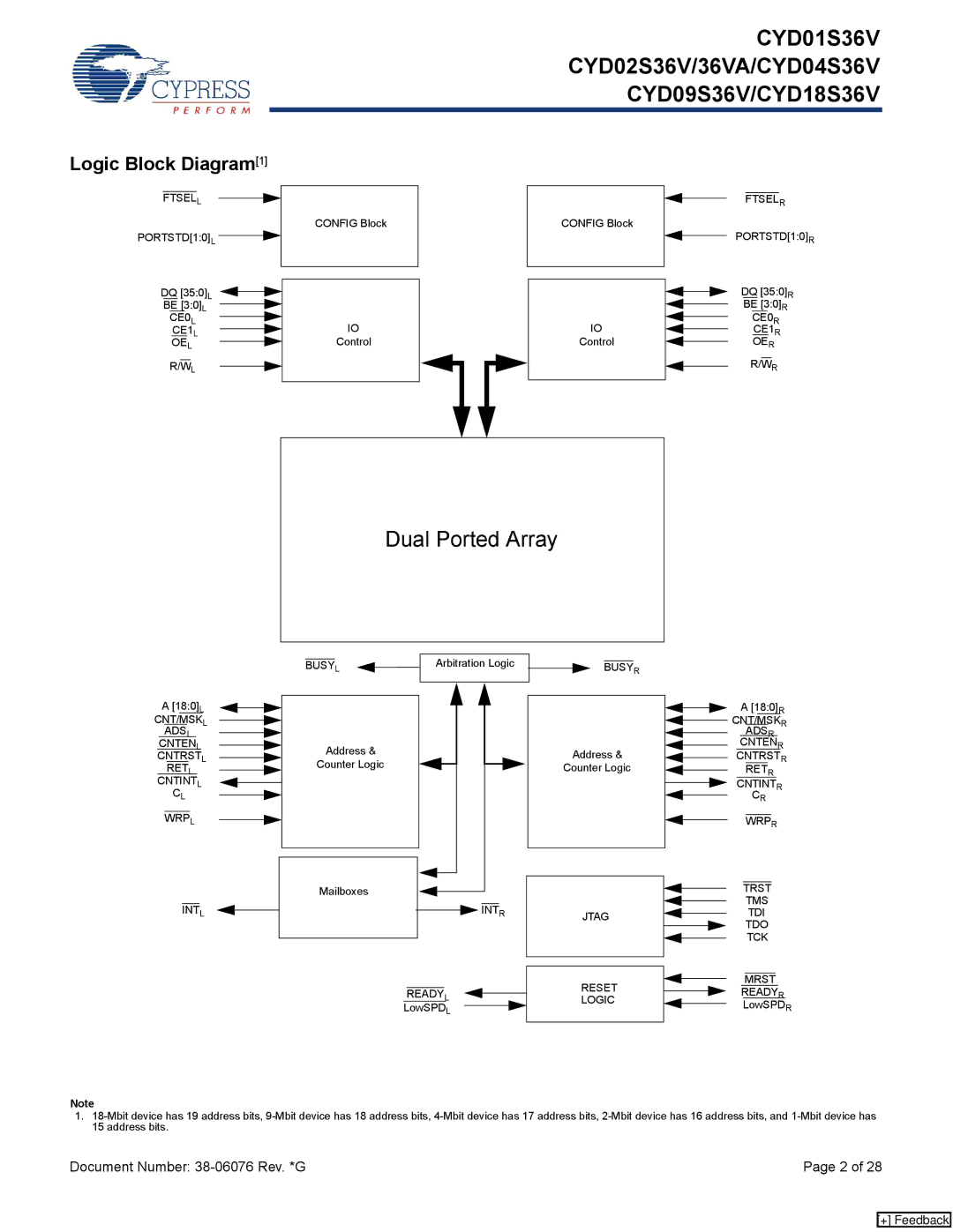
Logic Block Diagram[1]
CYD01S36V
CYD02S36V/36VA/CYD04S36V
CYD09S36V/CYD18S36V
FTSELL
PORTSTD[1:0]L ![]()
![]()
DQ [35:0]L
BE [3:0]L
CE0L
CE1L
OEL
R/WL
CONFIG Block
IO
Control
CONFIG Block
IO
Control
FTSELR
PORTSTD[1:0]R
DQ [35:0]R
BE [3:0]R
CE0R
CE1R
OER
R/WR
Dual Ported Array
A[18:0]L CNT/MSKL
ADSL CNTENL CNTRSTL RETL CNTINTL CL
WRPL
| L |
| Arbitration Logic | ||
BUSY |
| ||||
| |||||
|
|
|
|
|
|
|
|
|
|
|
|
Address &
Counter Logic
BUSYR
Address &
Counter Logic
A [18:0]R |
CNT/MSKR |
ADSR |
CNTENR |
CNTRSTR |
RETR |
CNTINTR |
CR |
WRPR |
INTL
Mailboxes
![]() INTR
INTR
READYL
LowSPDL
|
|
|
|
|
|
|
|
|
|
|
|
|
| TRST |
|
| |
|
|
|
| |||||
|
|
|
|
|
| TMS | ||
|
|
|
| |||||
JTAG |
|
|
|
|
| TDI | ||
|
|
| ||||||
|
|
|
|
| TDO | |||
|
|
|
|
|
| |||
|
|
|
|
|
| TCK | ||
|
|
|
| |||||
|
|
|
|
|
|
|
|
|
|
|
|
|
|
|
|
| |
|
|
|
|
|
|
|
| |
RESET |
|
|
|
|
| MRST | ||
|
|
|
| |||||
|
|
| READYR | |||||
|
|
| ||||||
LOGIC |
|
|
| |||||
|
|
|
| LowSPDR | ||||
|
|
|
|
| ||||
Note
1.
Document Number: | Page 2 of 28 |
[+] Feedback
