Manuals
/
Dell
/
Personal Care
/
Microscope & Magnifier
Dell
E20S001
owner manual
X8 hard-drive backplane Release pin Hooks
Models:
E20S
E20S001
1
64
163
163
Download
163 pages
49.17 Kb
61
62
63
64
65
66
67
68
Page 64
Image 64
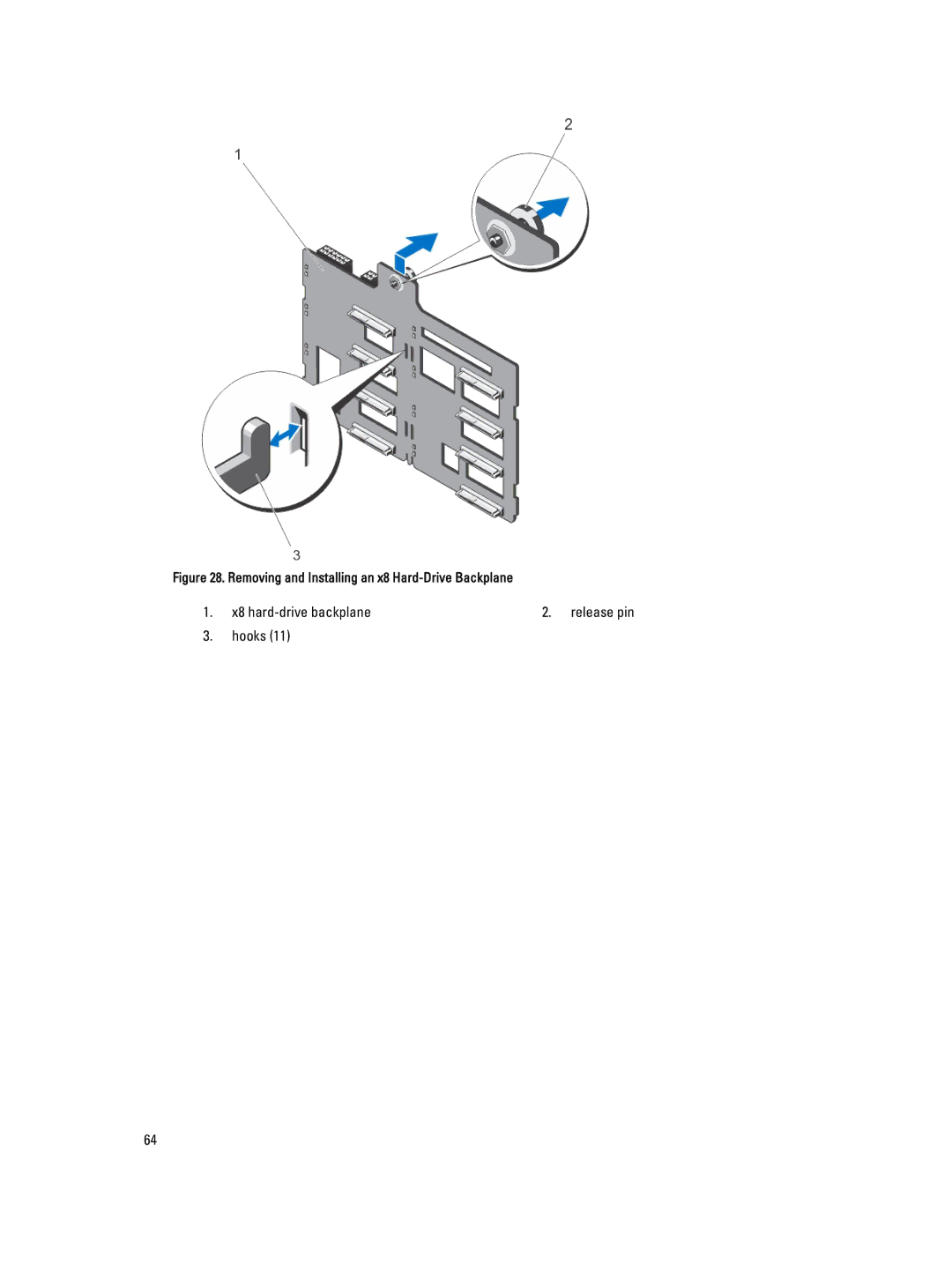
Figure 28. Removing and Installing an x8
Hard-Drive
Backplane
1.
x8
hard-drive
backplane
2. release pin
3.
hooks (11)
64
Page 63
Page 65
Page 64
Image 64
Page 63
Page 65
Contents
Regulatory Model E20S Series Regulatory Type E20S001
Dell Inc. All Rights Reserved
Contents
Installing System Components
Wheel Assembly Optional-Tower Mode
Installing The Hard-Drive Backplane
Converting The System From Tower Mode To Rack Mode
Troubleshooting Your System
Using System Diagnostics
Jumpers And Connectors
Technical Specifications
System Messages
163
Front-Panel Features And Indicators-Tower Mode
About Your System
Page
Indicator, Button, or Icon Description Connector
NMI button
One optional Sata DVD-ROM drive or DVD+/-RW drive
System to perform a graceful shutdown before
Front-Panel Features And Indicators-Rack Mode
Front-Panel Features and Indicators
LCD Panel Features
Setup Menu
Set error
Home Screen
Button Description
Diagnostic Indicators
View Menu
Electrical Indicator Condition
Hard-drive Indicator Condition
Memory Indicator Corrective Action
Hard-Drive Indicator Patterns
PCIe Indicator Condition
Error
Drive-Status Condition Indicator Pattern RAID Only
Back-Panel Features And Indicators
Seconds
PSU2
NIC Indicator Codes
Power Indicator Codes For Redundant Power Supply
Indicators are off Link indicator is
Amber Activity indicator is
Power Indicator Codes For Non-Redundant Power Supply
Other Information You May Need
Choosing The System Boot Mode
Keystroke Description
F10
F11 F12
Responding To Error Messages
Entering System Setup
Using The System Setup Navigation Keys
System Setup Options
System Setup Main Screen
System Bios Screen
System Information Screen
Memory Settings Screen
Processor Settings Screen
Option is set to Enabled
Prefetcher option is set to Enabled
Execute Disable
Execute Disable option is set to Enabled
Sata Settings Screen
Boot Settings Screen
Integrated Devices Screen
Serial Communications Screen
System Profile Settings Screen
System Security Screen
Miscellaneous Settings
System And Setup Password Features
Assigning a System And/Or Setup Password
Page
Using Your System Password To Secure Your System
Entering The Uefi Boot Manager
Operating With a Setup Password Enabled
Using The Boot Manager Navigation Keys
Boot Manager Screen
IDRAC Settings Utility
Uefi Boot Menu
Entering The iDRAC Settings Utility
Changing The Thermal Settings
Page
Recommended Tools
Installing The Front Bezel
Front Bezel Optional
Removing The Front Bezel
System Feet-Tower Mode
Removing The System Feet
Installing The System Feet
Wheel Assembly Optional-Tower Mode
Removing The Wheel Assembly
Installing The Wheel Assembly
Removing and Installing the Wheel Assembly
Opening And Closing The System
Opening The System
Inside The System
Closing The System
Power interposer board
Optical Drives And Tape Drives Optional
Slot Sata optical drive or PowerVault RD1000
Slot SAS tape drive or blank
Removing The Optical Drive Or Tape Drive
Optical drive
Connector for power cable extension
Cooling Shroud
Installing The Optical Drive Or Tape Drive
Removing The Cooling Shroud
Installing The Cooling Shroud
Removing and Installing the Cooling Shroud
Hard Drives-Hot-Swappable
Removing a Hot-Swap Hard Drive
Installing a Hot-Swap Hard Drive
Removing and Installing a Hot-Swap Hard Drive
Removing a 2.5 Inch Hard-Drive Blank
Installing a 2.5 Inch Hard-Drive Blank
Removing a 3.5 Inch Hard-Drive Blank
Installing a 3.5 Inch Hard-Drive Blank
Removing and Installing a 3.5 Inch Hard-Drive Blank
Inch hard drive
Hard-drive carrier Screws Hard drive
Hard Drives-Cabled
Installing and Removing the Internal Hard-Drive Bay
Removing The Internal Hard-Drive Bay
Installing The Internal Hard-Drive Bay
Removing a Cabled Hard Drive
Installing a Cabled Hard Drive
Removing and Installing a Cabled Hard Drive
Hard-Drive Backplane
Removing The Hard-Drive Backplane
X8 hard-drive backplane Release pin Hooks
SAS B connector
Power connector
X16 hard-drive backplane Release pin Hooks
Primary SAS connectors a and B
Installing The Hard-Drive Backplane
Cabling-x16 Hard-Drive Backplane With Expansion Card
Four-Slot Hard-Drive Blank
Removing a Four-Slot Hard-Drive Blank
Installing a Four-Slot Hard-Drive Blank
System Memory
Rdimm
Mode-Specific Guidelines
General Memory Module Installation Guidelines
Processor
Sample Memory Configurations
Advanced ECC Lockstep
Memory Configurations Single Processor
Removing Memory Modules
Ejecting The Memory Module
Installing Memory Modules
Removing The Memory Module
Installing The Memory Module
Cooling Fans
Removing The Internal Cooling Fan
Arrow
Installing The Internal Cooling Fan
Removing The External Cooling Fan
External cooling fan power cable
Internal USB Memory Key Optional
Installing The External Cooling Fan
Replacing The Internal USB Key
USB key USB connector
PCIe Card Holder Optional
Removing The PCIe Card Holder
Expansion Card Installation Guidelines
Installing The PCIe Card Holder
Expansion Cards
Removing An Expansion Card
GPU Card Installation Guidelines
Card Priority Card Type Slot Priority Maximum Allowed
Installing An Expansion Card
Removing and Installing the Expansion Card
Removing a GPU Card
Installing a GPU Card
Removing and Installing the GPU Card
IDRAC Ports Card
Removing The iDRAC Ports Card
Installing The iDRAC Ports Card
Removing and Installing the iDRAC Ports Card
Replacing An SD vFlash Card
Internal Dual SD Module
Removing An Internal Dual SD Module
Installing An Internal Dual SD Module
Internal SD Card
Processors
Installing An Internal SD Card
Removing An Internal SD Card
Removing a Processor
Heat sink
Installing a Processor
Removing and Installing a Processor
Redundant AC Power Supply
Removing a Redundant AC Power Supply
Installing a Redundant AC Power Supply
Removing The Power Supply Blank
Installing The Power Supply Blank
Replacing The Power Supply Divider
Removing and Installing the Power-Supply Divider
Non-Redundant AC Power Supply
Removing a Non-Redundant AC Power Supply
Non-redundant power supply
Installing a Non-Redundant AC Power Supply
Power Distribution Board And Power Interposer Board
Removing The Power Interposer Board
Power distribution board
System Battery
Installing The Power Interposer Board
Replacing The Power Distribution Board
Replacing The System Battery
Control-Panel Assembly
Removing and Installing the System Battery
Removing The Control-Panel Assembly
Control-panel assembly Control panel
111
Installing The Control-Panel Assembly
Removing The Control Panel
Control panel Control-panel board LCD module
Installing The Control Panel
LCD ZIF cable
116
Removing and Installing the LCD Module
Removing The LCD Module
Installing The LCD Module
Removing The VGA Module-Rack Mode
Installing The VGA Module-Rack Mode
System Board
Removing The System Board
Installing The System Board
Removing the System Board
Page
Converting The System From Tower Mode To Rack Mode
Safety Instructions
System top cover
Rack Installation
Removing and Installing the Rack Ears
Troubleshooting The Video Subsystem
Troubleshooting External Connections
Troubleshooting a USB Device
Troubleshooting a Serial I/O Device
Troubleshooting a NIC
Troubleshooting a Wet System
Troubleshooting a Damaged System
Troubleshooting The System Battery
Troubleshooting a Non-Redundant Power Supply
Troubleshooting Redundant Power Supplies
Troubleshooting Cooling Problems
Troubleshooting Cooling Fans
Troubleshooting System Memory
Troubleshooting An Internal USB Key
Troubleshooting An SD Card
Troubleshooting An Optical Or Tape Drive
Troubleshooting a Hard Drive
Troubleshooting Expansion Cards
Troubleshooting Processor
When To Use The Embedded System Diagnostics
Dell Online Diagnostics Dell Embedded System Diagnostics
Running The Embedded System Diagnostics
System Diagnostic Controls
Least one event description is recorded
System Board Jumper Settings
Jumper
System Board Jumpers And Connectors
Item Connector
Connector Description
ODD1/TBU
Disabling a Forgotten Password
Expansion slots
Expansion Bus
Memory
Drives
Connectors Back
Front
Expanded Operating Temperature
Connectors Internal
Video
Environmental Temperature
Temperature Continuous Operation
Relative Humidity
Maximum Vibration
Environmental
Gaseous Contamination
System Error Messages
LCD Messages
Viewing LCD Messages
Removing LCD Messages
Error Code
AMP0302 Message
Details
Action
ASR0003 Message
BAT0002 Message
BAT0017 Message
CPU0000 Message
CPU0010 Message
CPU0023 Message
CPU0204 Message
CPU0700 Message
CPU0703 Message
CPU0702 Message
CPU0704 Message
If the issue persists, see Getting Help
Action Reinstall or reconnect the hardware HWC2003 Message
FAN0000 Message
Details Fan operating speed is out of range Action
MEM0000 Message
MEM0001 Message
MEM0007 Message
MEM0701 Message
MEM1208 Message
MEM8000 Message
PCI1302 Message
PCI1304 Message
PCI1320 Message
PCI1342 Message
PCI1348 Message
PCI1360 Message
PST0128 Message
PST0129 Message
PSU0001 Message
PSU0002 Message
PSU0006 Message
PSU0016 Message
PSU0031 Message
PSU0032 Message
PSU0034 Message
PSU0035 Message
PSU0036 Message
PSU0037 Message
PSU1201 Message Power supply redundancy is lost Details
System power inventory change
Configuration and power consumption
System power consumption
RFM1014 Message
RFM1201 Message
RFM2001 Message
RFM2002 Message
SEL0006 Message All event logging is disabled Details
Appear if the user disabled event logging
Power. If problem persists call support
Security may be compromised
Issues persists, contact support
Failed
Failures
TMP0121 Message
Diagnostic Messages
Alert Messages
Getting Help
Contacting Dell
Top
Page
Image
Contents