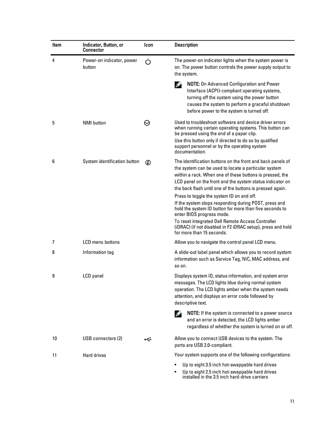
Item | Indicator, Button, or | Icon | Description |
| Connector |
|
|
|
|
|
|
4 |
| The | |
| button |
| on. The power button controls the power supply output to |
|
|
| the system. |
|
|
| NOTE: On Advanced Configuration and Power |
|
|
| Interface |
|
|
| turning off the system using the power button |
|
|
| causes the system to perform a graceful shutdown |
|
|
| before power to the system is turned off. |
5 | NMI button |
| Used to troubleshoot software and device driver errors |
|
|
| when running certain operating systems. This button can |
|
|
| be pressed using the end of a paper clip. |
|
|
| Use this button only if directed to do so by qualified |
|
|
| support personnel or by the operating system |
|
|
| documentation. |
6 | System identification button |
| The identification buttons on the front and back panels of |
|
|
| the system can be used to locate a particular system |
|
|
| within a rack. When one of these buttons is pressed, the |
|
|
| LCD panel on the front and the system status indicator on |
|
|
| the back flash until one of the buttons is pressed again. |
|
|
| Press to toggle the system ID on and off. |
|
|
| If the system stops responding during POST, press and |
|
|
| hold the system ID button for more than five seconds to |
|
|
| enter BIOS progress mode. |
|
|
| To reset integrated Dell Remote Access Controller |
|
|
| (iDRAC) (if not disabled in F2 iDRAC setup), press and hold |
|
|
| for more than 15 seconds. |
7 | LCD menu buttons |
| Allow you to navigate the control panel LCD menu. |
8 | Information tag |
| A |
|
|
| information such as Service Tag, NIC, MAC address, and |
|
|
| so on. |
9 | LCD panel |
| Displays system ID, status information, and system error |
|
|
| messages. The LCD lights blue during normal system |
|
|
| operation. The LCD lights amber when the system needs |
|
|
| attention, and displays an error code followed by |
|
|
| descriptive text. |
|
|
| NOTE: If the system is connected to a power source |
|
|
| and an error is detected, the LCD lights amber |
|
|
| regardless of whether the system is turned on or off. |
10 | USB connectors (2) |
| Allow you to connect USB devices to the system. The |
|
|
| ports are USB |
11 | Hard drives |
| Your system supports one of the following configurations: |
|
|
| • Up to eight 3.5 inch |
• Up to eight 2.5 inch
11