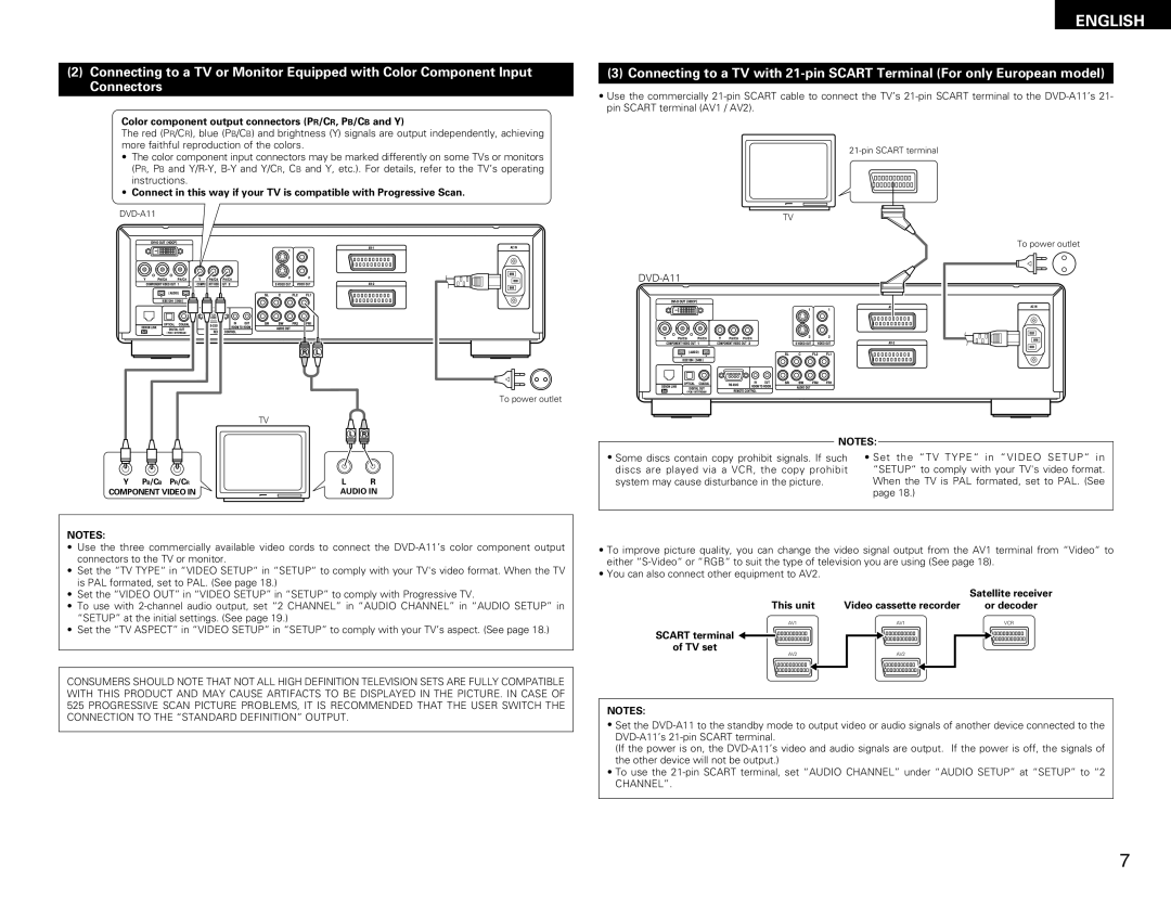
(2)Connecting to a TV or Monitor Equipped with Color Component Input Connectors
Color component output connectors (PR/CR, PB/CB and Y)
The red (PR/CR), blue (PB/CB) and brightness (Y) signals are output independently, achieving more faithful reproduction of the colors.
•The color component input connectors may be marked differently on some TVs or monitors (PR, PB and
•Connect in this way if your TV is compatible with Progressive Scan.
To power outlet
TV
Y PB/CB PR/CR |
|
|
| L | R |
COMPONENT VIDEO IN |
|
|
| AUDIO IN | |
|
|
|
|
|
|
ENGLISH
(3) Connecting to a TV with
•Use the commercially
TV
To power outlet
DVD-A11
NOTES:
• Some discs contain copy prohibit signals. If such | • Set the “TV TYPE“ in “VIDEO SETUP“ in |
discs are played via a VCR, the copy prohibit | “SETUP“ to comply with your TV's video format. |
system may cause disturbance in the picture. | When the TV is PAL formated, set to PAL. (See |
| page 18.) |
NOTES:
•Use the three commercially available video cords to connect the
•Set the “TV TYPE“ in “VIDEO SETUP“ in “SETUP“ to comply with your TV's video format. When the TV is PAL formated, set to PAL. (See page 18.)
•Set the “VIDEO OUT” in “VIDEO SETUP” in “SETUP” to comply with Progressive TV.
•To use with
•Set the “TV ASPECT” in “VIDEO SETUP” in “SETUP” to comply with your TV’s aspect. (See page 18.)
CONSUMERS SHOULD NOTE THAT NOT ALL HIGH DEFINITION TELEVISION SETS ARE FULLY COMPATIBLE WITH THIS PRODUCT AND MAY CAUSE ARTIFACTS TO BE DISPLAYED IN THE PICTURE. IN CASE OF 525 PROGRESSIVE SCAN PICTURE PROBLEMS, IT IS RECOMMENDED THAT THE USER SWITCH THE CONNECTION TO THE “STANDARD DEFINITION” OUTPUT.
•To improve picture quality, you can change the video signal output from the AV1 terminal from “Video“ to either
•You can also connect other equipment to AV2.
|
| Satellite receiver |
This unit | Video cassette recorder | or decoder |
AV1 | AV1 | VCR |
SCART terminal |
|
|
of TV set |
|
|
AV2 | AV2 |
|
NOTES:
•Set the
(If the power is on, the
•To use the
7