VENTING INSTALLATION INSTRUCTIONS | 9 |
Installation Planning (Cont.) |
VENTING INSTALLATION
INSTRUCTIONS
Continued
INSTALLATION PLANNING
There are two basic types of
•Horizontal Termination
•Vertical Termination
Horizontal Termination Installation
IMPORTANT: Horizontal square terminations require only inner portion of wall firestop. Horizontal installation using round termina- tion require exterior portion of wall firestop (see Figure 18, page 11).
1. Set the fireplace in its desired location and determine the route |
your horizontal venting will take. Do not secure the fireplace |
until all venting has been installed. Some installations require |
sliding the fireplace in and out of position to make final venting |
connections.Figures19through25onpages11through13show |
different configurations for venting with horizontal termina- |
tion that will help you decide which application best suits your |
installation. Check to see if wall studs or roof rafters are in the |
path of your desired venting route. If they are, you may want |
to adjust the location of the fireplace. |
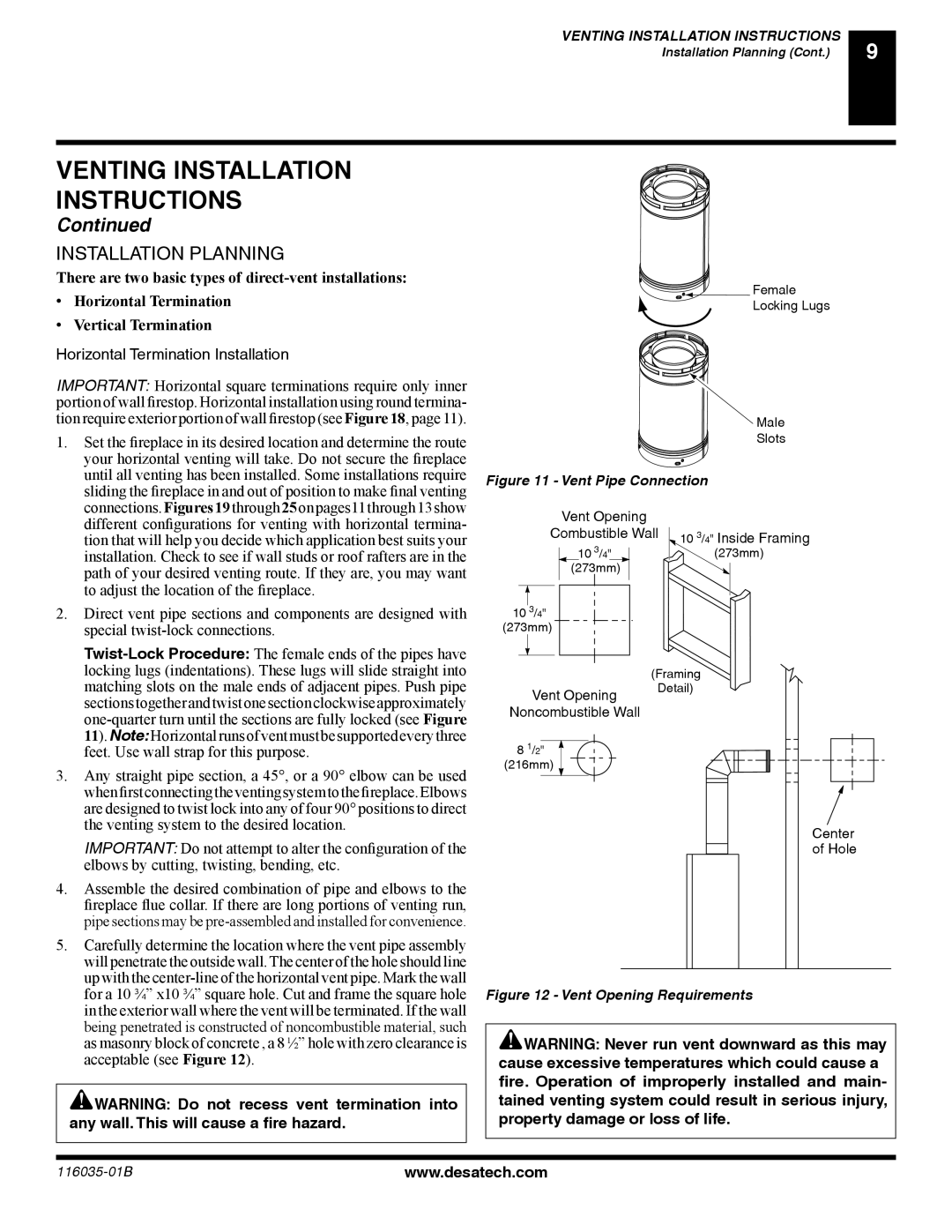
2. Direct vent pipe sections and components are designed with |
special |
locking lugs (indentations). These lugs will slide straight into |
Female
Locking Lugs
Male
Slots
Figure 11 - Vent Pipe Connection
Vent Opening
Combustible Wall ![]() 10 3/4" Inside Framing
10 3/4" Inside Framing
10 3/4"(273mm) (273mm)
10 3/4" (273mm)
(Framing
matching slots on the male ends of adjacent pipes. Push pipe |
sectionstogetherandtwistonesectionclockwiseapproximately |
Vent Opening
Detail)
11).Note:Horizontalrunsofventmustbesupportedeverythree |
feet. Use wall strap for this purpose. |
3. Any straight pipe section, a 45°, or a 90° elbow can be used |
whenfirstconnectingtheventingsystemtothefireplace.Elbows |
are designed to twist lock into any of four 90° positions to direct |
the venting system to the desired location. |
IMPORTANT: Do not attempt to alter the configuration of the |
elbows by cutting, twisting, bending, etc. |
4. Assemble the desired combination of pipe and elbows to the |
fireplace flue collar. If there are long portions of venting run, |
pipe sections may be |
5. Carefully determine the location where the vent pipe assembly |
will penetrate the outside wall. The center of the hole should line |
up with the |
for a 10 ¾” x10 ¾” square hole. Cut and frame the square hole |
in the exterior wall where the vent will be terminated. If the wall |
being penetrated is constructed of noncombustible material, such |
as masonry block of concrete , a 8 ½” hole with zero clearance is |
acceptable (see Figure 12). |
![]() WARNING: Do not recess vent termination into any wall. This will cause a fire hazard.
WARNING: Do not recess vent termination into any wall. This will cause a fire hazard.
Noncombustible Wall
8 1/2"
(216mm)
Center
of Hole
Figure 12 - Vent Opening Requirements
![]() WARNING: Never run vent downward as this may cause excessive temperatures which could cause a fire. Operation of improperly installed and main- tained venting system could result in serious injury, property damage or loss of life.
WARNING: Never run vent downward as this may cause excessive temperatures which could cause a fire. Operation of improperly installed and main- tained venting system could result in serious injury, property damage or loss of life.
www.desatech.com |