20 | INSTALLING OPTIONAL CONTROLS |
Installing Optional Wall Mount Switch - GWMS2 |
Installing Optional Wireless
INSTALLING OPTIONAL CONTROLS
INSTALLING OPTIONAL WALL MOUNT SWITCH - GWMS2
1.Connect one terminal of 15 ft. wire from the wall switch to the TPTH terminal on the valve. Connect remaing wire terminal to the TH terminal on the valve. Make sure that the wire termi- nals are in the positions on the unit as pictured in Figure 41. If wires are not connected as shown the switch will not work.
2.Route the 15 ft. wire through hole openings with bushings provided on either side of the fireplace cabinet.
3.Connect one bare wire end to each of the terminals of the GWMS2 wall switch.
4.Install the wall switch and cover in the wall.
IMPORTANT: Do not use any other wire than that provided with the GWMS2 wall switch kit. Do not exceed 15 ft. of distance from the valve connection. Using wire of higher gage or turns or exceeding the minimum distance will increase resistance at the control valve causing unreliable performance of the fireplace controls.
To Optional Remote Receiver or a Wall Switch Accessory
Figure 41 - Connecting Remote Receiver or Wall Switch to the Gas Control Valve
INSTALLING OPTIONAL WIRELESS
Installing Remote Receiver
1.Open bottom louver and locate the switch bracket on the right
2.Locate the battery clip mounted on the back of the receiver. Slide a
3.Attach the terminal wires to the battery. (see Figure 42).
4.Connect wires from receiver to TH and TPTH to control valve (see Figure 41).
5.Locate the two plastic mounting clips provided with the kit.
6.Use the clips to mount the receiver on remote mounting bracket. as shown in Figure 43.
Installing
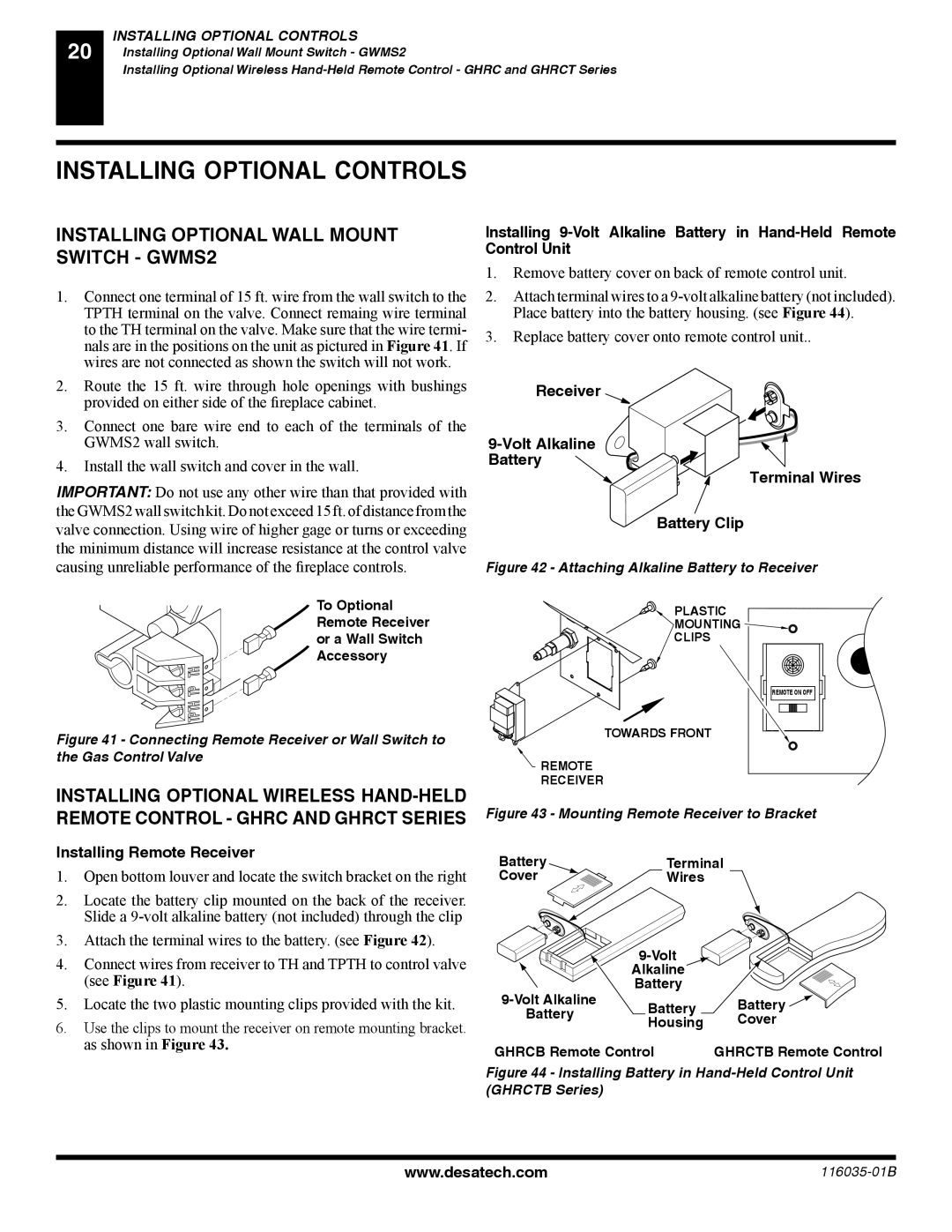
1.Remove battery cover on back of remote control unit.
2.Attach terminal wires to a
3.Replace battery cover onto remote control unit..
Receiver
9-Volt Alkaline
Battery
Terminal Wires
Battery Clip
Figure 42 - Attaching Alkaline Battery to Receiver
PLASTIC
MOUNTING ![]()
CLIPS
REMOTE ON OFF ![]()
![]()
![]()
TOWARDS FRONT
![]() REMOTE
REMOTE
RECEIVER
Figure 43 - Mounting Remote Receiver to Bracket
Battery | Terminal | ||
Cover | Wires |
| |
|
| ||
| Alkaline |
| |
Battery |
| ||
Battery | Battery | ||
Battery | |||
Housing | Cover | ||
| |||
GHRCB Remote Control | GHRCTB Remote Control | ||
Figure 44 - Installing Battery in Hand-Held Control Unit (GHRCTB Series)
www.desatech.com |