VENTING INSTALLATION INSTRUCTIONS | 11 |
Installation Planning (Cont.) |
VENTING INSTALLATION
INSTRUCTIONS
Continued
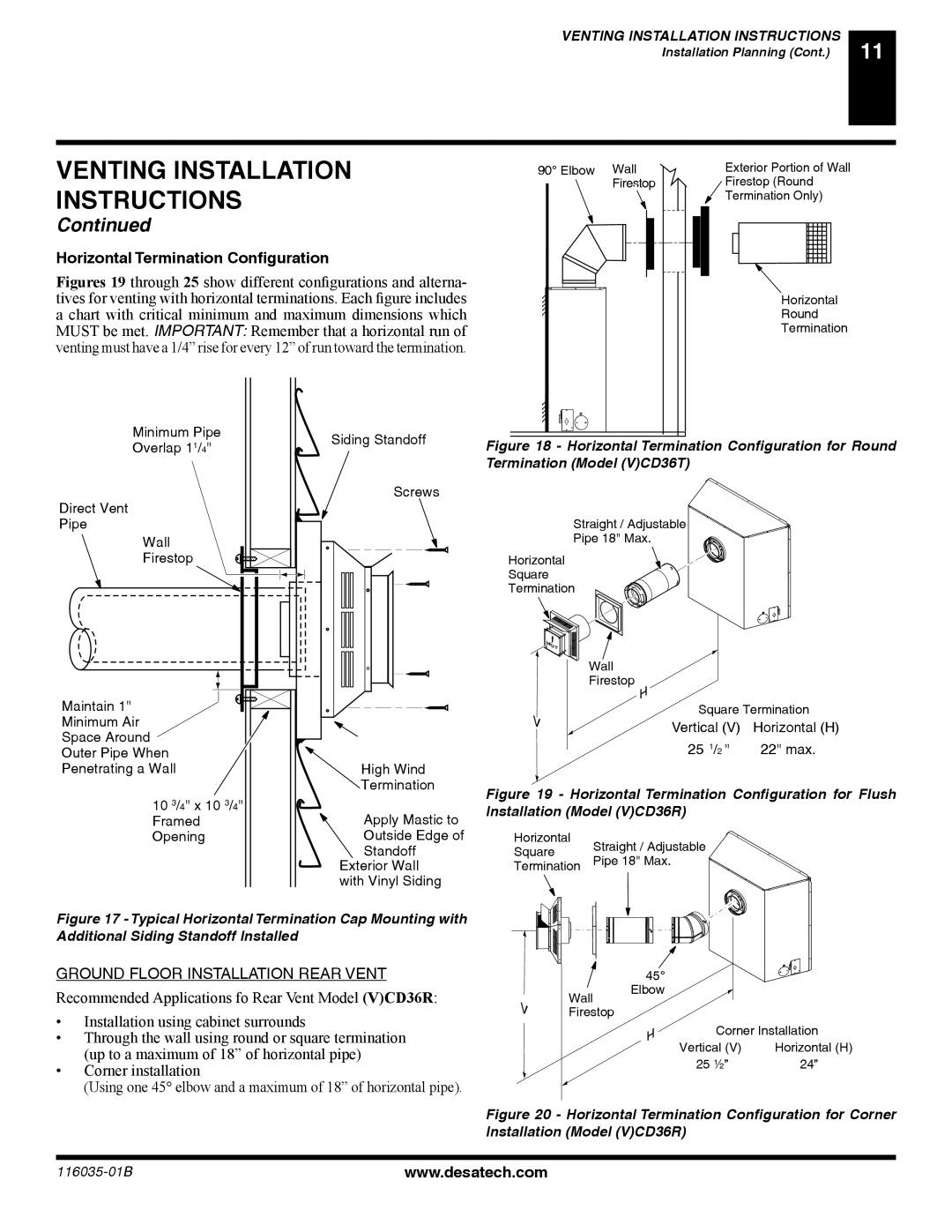
Horizontal Termination Configuration
Figures 19 through 25 show different configurations and alterna- tives for venting with horizontal terminations. Each figure includes a chart with critical minimum and maximum dimensions which MUST be met. IMPORTANT: Remember that a horizontal run of venting must have a 1/4” rise for every 12” of run toward the termination.
Minimum Pipe | Siding Standoff | |
Overlap 11/4" | ||
| ||
| Screws | |
Direct Vent |
| |
Pipe |
| |
Wall |
| |
Firestop |
|
Maintain 1" |
|
Minimum Air |
|
Space Around |
|
Outer Pipe When |
|
Penetrating a Wall | High Wind |
| Termination |
10 3/4" x 10 3/4" | Apply Mastic to |
Framed | |
Opening | Outside Edge of |
| Standoff |
| Exterior Wall |
| with Vinyl Siding |
Figure 17 - Typical Horizontal Termination Cap Mounting with Additional Siding Standoff Installed
90° Elbow Wall | Exterior Portion of Wall |
Firestop | Firestop (Round |
| Termination Only) |
Horizontal
Round
Termination
Figure 18 - Horizontal Termination Configuration for Round Termination (Model (V)CD36T)
Straight / Adjustable
Pipe 18" Max.
Horizontal
Square
Termination
Wall
Firestop
Square Termination
Vertical (V) Horizontal (H)
25 1/2 " | 22" max. |
Figure 19 - Horizontal Termination Configuration for Flush Installation (Model (V)CD36R)
Horizontal | Straight / Adjustable | |
Square | ||
Pipe 18" Max. | ||
Termination |
GROUND FLOOR INSTALLATION REAR VENT
Recommended Applications fo Rear Vent Model (V)CD36R:
•Installation using cabinet surrounds
•Through the wall using round or square termination (up to a maximum of 18” of horizontal pipe)
•Corner installation
(Using one 45° elbow and a maximum of 18” of horizontal pipe).
Wall Firestop
45° Elbow
Corner Installation
Vertical (V) | Horizontal (H) |
25 ½” | 24” |
Figure 20 - Horizontal Termination Configuration for Corner Installation (Model (V)CD36R)
www.desatech.com |