D55690, D55695
Pump Air Intake Filter B. Engine Air Filter
Air Compressor
D55695
Pump Specifications
Engine Specifications
Specifications
Hot Surfaces
Definitions Safety Guidelines
Important Safety Instructions
What can happen How to prevent it
Save these instruction
What can happen
Transporting or storing
Fly apart, and could result in serious injury
Attachments & accessories
Tires
Always wear certified safety
Maintenance until unit has
Attempting maintenance
Equipment Ansi Z87.1 eye
By a DeWALT factory service
Service center
Moving parts such as
Your clothing
Important Safety Instructions for All Battery Packs
Read all Instructions
Specific Safety instructions for Lithium Ion Li-Ion
Rbrc Seal
Important Safety Instructions for all Battery Chargers
Wire Size AWG
25 ft 50 ft 75 ft 100 ft 125 ft 150 ft 175 ft
Do not operate charger with damaged cord or plug
Using Automatic Tune-Up Mode
Charging Procedure
Indicator Light Operation
Chargers
Charge Indicators
Hot/cold Pack DelaY
Problem Power Line
Leaving the battery pack in the charger
Safety Valve
Features
Storage Recommendations
Assembly Fig
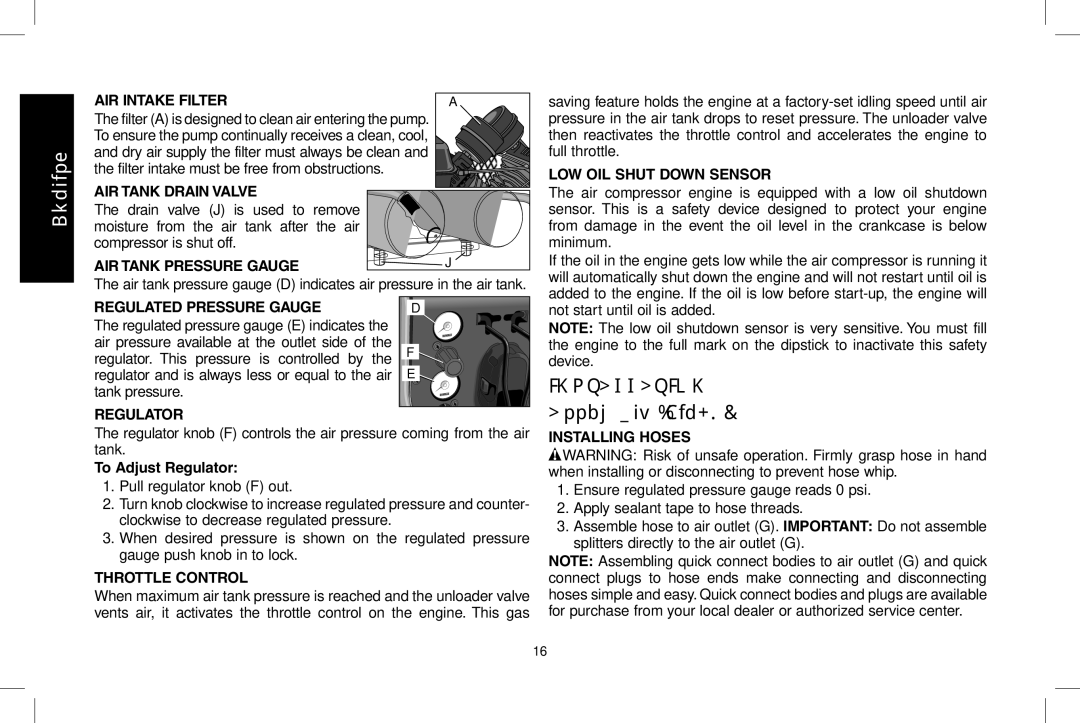
AIR Intake Filter
AIR Tank Drain Valve
Regulated Pressure Gauge
Location
Compatibility
Transporting
Preparation For Use Pre-Start Checklist Fig
Initial Set-up Fig
Lifting
Kg Do not move or lift without assistance
Procedure
Break-in Procedure This procedure is required
Recoil Start
Follow Pre-Start Checklist under Preparation for Use
Operating Procedures Start-up Fig
Turn the engine START/RUN/OFF switch C to the RUN position
Maintenance
Maintenance Chart
Procedure Daily Weekly Monthly Year or
Shut-down
Checking Air Filter Element Fig
Checking Safety Valve Fig
Draining Air Tank Fig
Compressor Pump Oil Fig
Air tank causing a risk of air tank rupture
Checking oil Changing oil
Checking Belt Tension Fig
Adjusting Belt Tension
Pulley and Flywheel Alignment
Accessories Service Information
Full One Year Warranty
Repairs
Date and Place of Purchase
Glossary
Troubleshooting Guide
Problem Code
Troubleshooting Codes
Possible Solution
Code Possible cause
Erwise modify air tank or it will weaken. The air tank can
See Motor Pulley/Flywheel Alignment under Maintenance
Compressor Pump Oil under Maintenance
Regulator open Engine fuel tank empty
Procedure
Push knob in to lock in place
Compresseur d’air
Caractéristiques techniques de la pompe
Caractéristiques techniques du moteur
Surfaces chaudes
Fiche technique
Définitions lignes directrices en Matière de sécurité
Directives de sécurité importantes
Mineures ou modérées
Composer Sans Frais LE 1-800-4-DeWALT
CE QUI Peut SE Produire
Installer correctement des
Filtres convenables et un
Du compresseur ne devrait
Jamais être utilisé pour
CE QUI Peut SE Produire Comment L’ÉVITER
Pneus
Attachements et accessoires
Le manomètre pour empêcher un surgonflage
Des accessoires
De sécurité homologué
CSA Z94.3 munie d’écrans
Compresseur
Ne jamais utiliser le
Ou les couvercles sont
Endommagés ou retirés
Garder les cheveux, les
Lire toutes les directives
Avertissement Risque d’incendie. Ne pas
Le sceau Srprc
Calibre AWG
25 pi
NE Jamais tenter de relier deux chargeurs ensemble
Utilisation du mode tune-up automatique
Chargeurs
Procédure de charge
Fonctionnement du voyant Voyants de charge
Remarques importantes pour le chargement
Fonction de suspension du bloc-piles chaud/froid
Problème avec le secteur
Bloc-piles laissé dans le chargeur
Recommandations d’entreposage
Caractéristiques
Démarrage Électrique
BLOC-PILES ET Chargeur DE 18 Volts
Soupape DE Sûreté
Filtre D’ADMISSION D’AIR
Soupape DE Purge DU Réservoir D’AIR
Manomètre DU Réservoir D’AIR
Assemblage fig
Emplacement
Compatibilité
Transport
Déplacement
REMARQUE
Réglage initial fig
Mode d’emploi Liste de vérification de pré-démarrage fig
Procédure de rodage La procédure suivante est requise
Démarrage à rappel
Démarrage électrique
Procédures de fonctionnement Démarrage fig
Arrêt
Entretien
Régulateur sous Caractéristiques
Étapes 3 à
Vérification de la soupape de sûreté fig
Programme d’entretien
Vérification des éléments du filtre d’air fig
Huile de la pompe du compresseur fig
Vidange du réservoir d’air fig
Vérification de l’huile
Vérification de la tension de la courroie Fig
Vidange d’huile
Réglage la tension de la courroie
Alignement de la poulie et du volant
Réparations
Accessoires Information sur les réparations
Garantie complète d’un 1 an
Glossaire
Guide de dépannage
Problème Code
13, 14, 16, 19
Sifflement
Est requis pour l’utilisation de l’accessoire
Codes de dépannage
Code Cause possible
Rompre ou d’exploser
Réglage de la tension de la courroie sous Entretien
Avertissement Risque d’éclatement. Des vibrations
Fixation bien serrées
Ne jamais utiliser l’appareil sans le support du raidisseur
Volant sous Entretien
Consulter la rubrique Alignement de la poulie-moteur
Compresseur sous Entretien
Ouverte
D55690A
Compresor de aire
Tapón de drenaje de aceite de la bomba
Especificaciones de la bomba
Especificaciones del motor
Superficies calientes
Especificaciones
Instrucciones de seguridad importantes
Guarde estas instrucciones
Peligro Riesgo de explosión o incendio
¿Qué puede suceder? Cómo evitarlo
Peligro Riesgo Respiratorio asfixia
Advertencia Riesgo de explosión
¿Qué puede suceder?
Elementos y accesorios
Neumáticos
Neumático
Advertencia Riesgo por piezas móviles
Advertencia Riesgo de operación insegura
Lea todas las instrucciones
Advertencia Riesgo de incendio. No guarde
Sin embargo, si el sello externo está roto
El sello Rbrc
Utilización del modo Tune-Up automático
Pies 50 pies
Tamaño AWG del conductor
Nunca intente conectar 2 cargadores juntos
Cargadores
Procedimiento de carga
Operación de la luz indicadora Indicadores de carga
Retraso por paquete caliente/frío
Notas importantes sobre la carga
Línea de potencia con problemas
Dejar el paquete de baterías en el cargador
Recomendaciones con respecto al almacenamiento
Características
Arranque Eléctrico
Paquete DE Baterías Y Cargador DE 18
Ensamblaje Fig
Filtro DE Entrada DE Aire
Válvula DE Drenaje DEL Tanque DE Aire
Manómetro Regulado
Compatibilidad
Lubricación y aceite
Lugar
Áreas húmedas
Consideraciones sobre el ruido
Transporte
Levantar la unidad
Configuración inicial Fig
Arranque de retroceso
Arranque eléctrico
Procedimientos operativos Puesta en marcha Fig
Apagado
Mantenimiento
Tabla de mantenimiento
Controlar la válvula de seguridad Fig
Controlar el elemento del filtro de aire
Procedimiento
Drenar el tanque de aire Fig
Aceite de la bomba del compresor
Coloque el elemento nuevamente en la base del filtro
Controlar el aceite
Controlar la tensión de la correa Fig
Cambio de aceite
Ajustar la tensión de la correa
Alineación de la correa y el volante
OFF apagado Espere que la unidad
Se enfríe Desconecte el cable de La bujía Drene Tanque Aire
Accesorios
Información del servicio técnico
Reparaciones
Póliza de Garantía
Garantía completa de un año
Excepciones
Glosario
Para Otras Localidades
Guía de detección de problemas
Problema Código
Códigos de detección de problemas
Código Causa posible
Solución Posible
Advertencia Riesgo de explosión. No perfore, suelde ni
Tornillos de montaje se deben mantener ajustados
Que esté equipada con el soporte de la barra tensora
Consulte Alineación de la polea y el volante en la sección
Mantenimiento
Consulte Aceite de la bomba del compresor en la sección
Tanque de combustible del motor vacío
Al de instrucciones del motor
JUN08 Part No. N000707
EWALT Industrial Tool Co., 701 Joppa Road, Baltimore, MD
Copyright 2008 D eWALT