5 | Establishing network |
| connections |
Connectors and cables
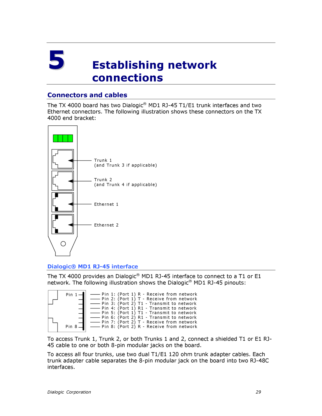
The TX 4000 board has two Dialogic® MD1
4000 end bracket:
T ru n k 1
(a nd Trunk 3 if applica ble)
Trunk 2
(a nd Trunk 4 if applica ble)
Ethernet 1
Ethernet 2
Dialogic® MD1 RJ-45 interface
The TX 4000 provides an Dialogic® MD1
Pin 1
Pin 8
Pin 1: (P ort 1) R - Receiv e fr om n e tw ork
Pin 2: (P ort 1) T - Re ceive from ne twor k
Pin 3 : (P ort 2 ) T1 - Tr a n s m it to n e twor k
Pin 4 : (P ort 1 ) R1 - T ra n s m it to n e tw ork
Pin 5 : (P ort 1 ) T1 - Tr a n s m it to n e twor k
Pin 6 : (P ort 2 ) R1 - T ra n s m it to n e tw ork
Pin 7: (P ort 2) T - Re ceive from ne twor k
P i n 8: (P ort 2) R - Receiv e fr om n e tw ork
To access Trunk 1, Trunk 2, or both Trunks 1 and 2, connect a shielded T1 or E1 RJ- 45 cable to one or both
To access all four trunks, use two dual T1/E1 120 ohm trunk adapter cables. Each trunk adapter cable separates the
Dialogic Corporation | 29 |
