Establishing network connections | TX 4000 PCI SS7 Network Interface Board Installation Manual |
E1 network considerations
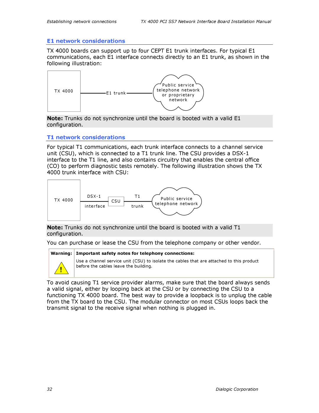
TX 4000 boards can support up to four CEPT E1 trunk interfaces. For typical E1 communications, each E1 interface connects directly to an E1 trunk, as shown in the following illustration:
T X 4 0 0 0
| P u b li c s e r v ic e | |
E 1 t r u n k | t e l e p h o n e n e t w o r k | |
o r p r op ri e ta r y | ||
| ||
| n e tw o r k |
Note: Trunks do not synchronize until the board is booted with a valid E1 configuration.
T1 network considerations
For typical T1 communications, each trunk interface connects to a channel service unit (CSU), which is connected to a T1 trunk line. The CSU provides a
4000 trunk interface with CSU:
T X 4 0 0 0
D S X - 1
in ter f ace
C S U
T 1 | Pu b lic se rv ice |
| |
tru n k | tele p h on e n e tw or k |
|
Note: Trunks do not synchronize until the board is booted with a valid T1 configuration.
You can purchase or lease the CSU from the telephone company or other vendor.
Warning: Important safety notes for telephony connections:
Use a channel service unit (CSU) to isolate the cables that are attached to this product before the cables leave the building.
To avoid causing T1 service provider alarms, make sure that the board always sends a valid signal, either by looping back at the CSU or by connecting the CSU to a functioning TX 4000 board. The best way to provide a loopback is to unplug the cable from the TX board to the CSU. The modular connector on most CSUs loops back the transmit signal to the receive signal when nothing is plugged in.
32 | Dialogic Corporation |
