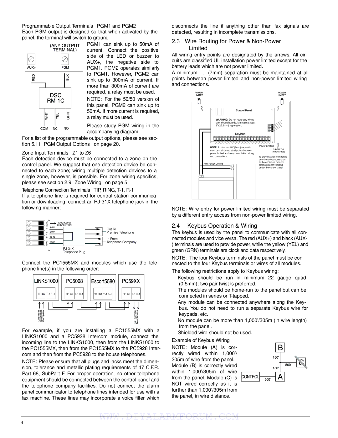
PC1555MX specifications
The DSCover Satellite Products PC1555MX is an advanced satellite communication device designed to meet the demands of both commercial and industrial sectors. Its high-performance capabilities are complemented by a robust design, making it an excellent choice for users who require reliable connectivity in remote or challenging environments.At the heart of the PC1555MX is its cutting-edge satellite technology, which enables seamless communication regardless of geographical constraints. The device operates on multiple frequency bands, enhancing its versatility and ensuring optimal performance in diverse conditions. This multi-band capability allows for greater flexibility in communication, accommodating various applications from data transmission to voice calls.
One of the standout features of the PC1555MX is its impressive data transfer speeds. With advancements in modulation techniques, users can enjoy fast and efficient data upload and download rates. This makes the device particularly suitable for applications that require real-time data processing, such as telemetry, remote monitoring, and emergency response communications.
The PC1555MX also incorporates advanced encryption protocols to ensure data security during transmission. This is especially crucial for industries such as defense, security, and finance, where sensitive information must be safeguarded against potential breaches. Users can have peace of mind knowing that their communications are protected by state-of-the-art security measures.
In addition to its communication capabilities, the PC1555MX is designed with user-friendly operation in mind. Its intuitive interface allows for easy navigation and control, making it accessible even to those with limited technical expertise. Furthermore, the device is equipped with a comprehensive alert system that notifies users of any connectivity issues or performance deviations, ensuring that they remain informed and can take swift action if necessary.
Durability is another key characteristic of the DSCover PC1555MX. Built to withstand harsh environmental conditions, it features a rugged exterior that is both weather-resistant and shockproof. This level of durability makes the device suitable for deployment in various settings, from outdoor expeditions to industrial sites.
Overall, the DSCover Satellite Products PC1555MX stands out as a premier choice for satellite communication. With its advanced features, robust design, and commitment to security and performance, it effectively meets the needs of users in an increasingly connected world. Whether for business operations or emergency services, the PC1555MX ensures that critical communications remain uninterrupted.

