Little Board/486e Computer
Revision Reason for Change Date
Table of Contents
Page
Technical Specifications
Index
Technical Support
Introduction
This page left intentionally blank Viii
CPU/Motherboard
Features
Chapter
General Description
VL-Bus Flat Panel/CRT Display Controller
Enhanced Embedded-PC Bios
IDE Interface
Serial Ports
Enhanced Parallel Port
Floppy Interface
Byte-Wide Socket and Solid State Disk SSD
Ethernet LAN Interface
Modular PC/104 Expansion Bus
Enhanced Reliability
Halt Testing
Software
Little Board Development Platform
Overview
Interface Connector Summary
Connectors
Connector Function Size Key Pin
Connector and Jumper Locations
Jumper Configuration Options
Jumper Group Function Default
System I/O Map
Address Function
DC Power
Connector Type Mating Connector
Pin Connection
Power Requirements
Backup Battery
Cooling Requirements
Powerfail Monitor
System Memory Map
Dram
Memory Address Function
Expanded Memory and Extended Memory
Addresses
Serial Ports J11, J13
RS-232C Serial Ports
RS-485 Serial Port
IRQ11 IRQ7
Interrupt Assignments
Serial Port Connectors J11, J13
ROM-BIOS Installation of the Serial Ports
Name Pin
Ports Pin Signal Function In/Out DB25
Pin Signal Name
Configuring Serial 2 for RS-485 J6, W5, W6
Pin RJ11 Signal Standard Wire Color
RS-485 Twisted-Pair Cabling Using RJ11 Connectors
Interconnection Scheme Examples
Using the RS-485 Interface
Serial Console
Hex Command
Serial Handshake
COM Port Table
Using a Serial Modem
Serial Booting and Serial Programming
Bi-Directional Parallel Port
Register Name Address Primary Secondary
Selection Address Interrupts
ROM-BIOS Installation of Parallel Ports
Signal Type Number of Lines Function Output Drive
Standard and General Purpose I/O Operation
Parallel Port Interrupt
Parallel Port Interrupt Enable
Register Bit Signal Name In/Out Active J15
Or Function High/Low Pin
J15 Pin Signal Function In/Out DB25 Name
Parallel Port Connector J15
Register Bit Definitions
Signal Name Full Name Description
Floppy Disk Interface
Floppy Drive Considerations
Capacity Drive Size Tracks Data Rate
Floppy Interface Configuration
Floppy Interface Connector J14
Pin Signal Name Function In/Out
IDE Hard Disk Interface
IDE Connector J12
25. IDE Drive Interface Connector J12
IDE Interface Configuration
Solid-State Disk Preparation
Master/Slave Setting
Compact Flash Solid-State Disk
Enabling the Drive
Connecting a CRT J5
Name Connector Pins/Type Description
Flat Panel/CRT Video Controller
Part Description Mating Connector
J5 Pin Signal Name DB-15 DB-9
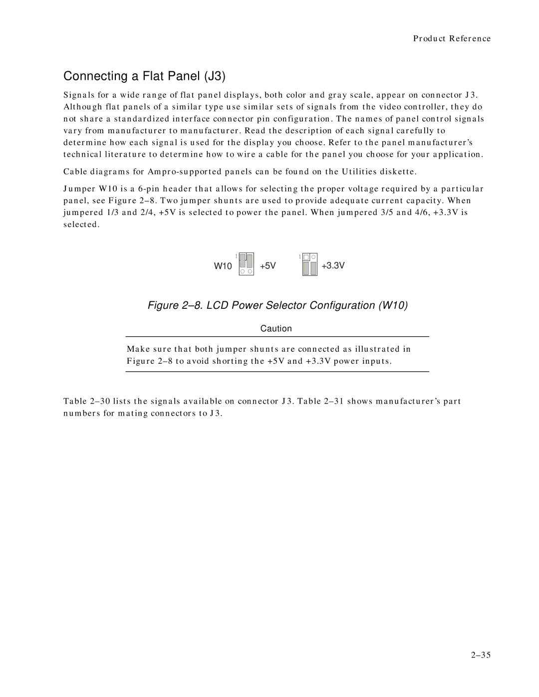
W10 +5V
Connecting a Flat Panel J3
FLM
Pin Signal Description Name
Advanced Power Management
Power Sequencing
Pgmebios VIDEO=filename
Bios Support of Non-Standard Panels
Selecting Vee Polarity
LCD Bias Supply Option
J4 Pin J3 Pin Description
Ra = 270 Rb = Vee max Vee min / 1.5
Attaching an External Contrast Control
Example
Network Terms
Ethernet Network Interface
QNX
Installing an Ethernet Boot Prom
Twisted Pair Interface J7
Twisted-Pair Installations
Installing a Boot Prom
Installing a Boot Prom in Byte-Wide Socket S0
Using Network Operating Systems NOS
Network OS Drivers
Controlling the Ethernet LAN Interface Directly
Program Name Vendor Function Driver Name
00 40
Manufacturer’s Ethernet ID
Byte-Wide Socket S0
SSD Device Size Package Generic Type Pins Part Number
ROM-BIOS Extensions
Addressing the Byte-wide Socket
Window Address
Accessing the Byte-Wide Socket
Performance Issues
Solid State Disk SSD Drives
Device 64KB Segment Address Size Segments Upper Nibble of BH
Jumpering the Byte-Wide Socket
Byte-Wide Socket Signals
Typical Devices Pins Jumper Diagram
W14 Pin Signal Name Description
Using EPROMs
Flash Eprom Typical Devices Pins Jumper Diagram
Flash Eprom Programming
Non-volatile RAM
Using SRAMs
Utility Connector J16
Exsmi
Pin Signal Name Function
LED Connection
Push Button Reset Connection
External Battery Connections
PC Speaker
Battery-Backed Clock
Watchdog Timer
Jumper W4
WDT Response
AL,61H AL,NOT 08H OUT 61H,AL
Page
AT Expansion Bus
Onboard MiniModule Expansion
Using Standard PC and AT Bus Cards
Bus Termination
Bus Expansion Guidelines
Expansion Bus Connector Pinouts
PU/PD/S
Pin Signal Function In/Out Current
47. AT Expansion Bus Connector, B1-B32 P1
48. AT Expansion Bus Connector, C0-C19 P2
PU/PD/S
Interrupt Function
Interrupt and DMA Channel Usage
Channel Function
Serial Parallel Floppy
Ethernet Video
Setup Overview
Menu Name Functions
Standard CMOS/EEPROM Setup
Setup Page 1-Standard CMOS/EEPROM Setup
IDE Hard Disk Drives
Drive Parameter Setup
Date and Time
Floppy Drives
Page
System Post
Error Halt
Video
Dram Memory
Extended Bios
Setup Page 2-Options/Peripheral Configuration
Selection Address Interrupt
Serial Port
Parallel Port
Port Address
Selection Address
Floppy Interface Enable
IDE Interface Enable
Hot Key Setup Enable
Blank Post Test
Video State
Local Bus Video Display
Byte-Wide Socket Configuration
Serial Boot Loader Enable
Watchdog Timer Configuration
Flat Panel Display Type
Installing a Modified Bios to Support a New Panel
Extended Serial Console Configuration
Setup Page 3-Serial Console Configuration
Page
Switch Function
Creating Configuration Files with SETUP.COM
DIR LPT1
Operation with DOS
Utility Software Overview
Embedded-PC System Enhancements
Little Board/486e CPU Specifications
Onboard Peripherals
CRT Support for Standard Video Modes
Vesa
Font Pixels Clock Horiz Vert Mem Mode MHz KHz
Support Software
Mechanical and Environmental Specifications
Mechanical Dimensions
Technical Specifications
Page
Index
Page
POST, Setup
Little Board/486e Technical Manual Index-4