Little Board™/486e Technical Manual
Jumper Configuration Options
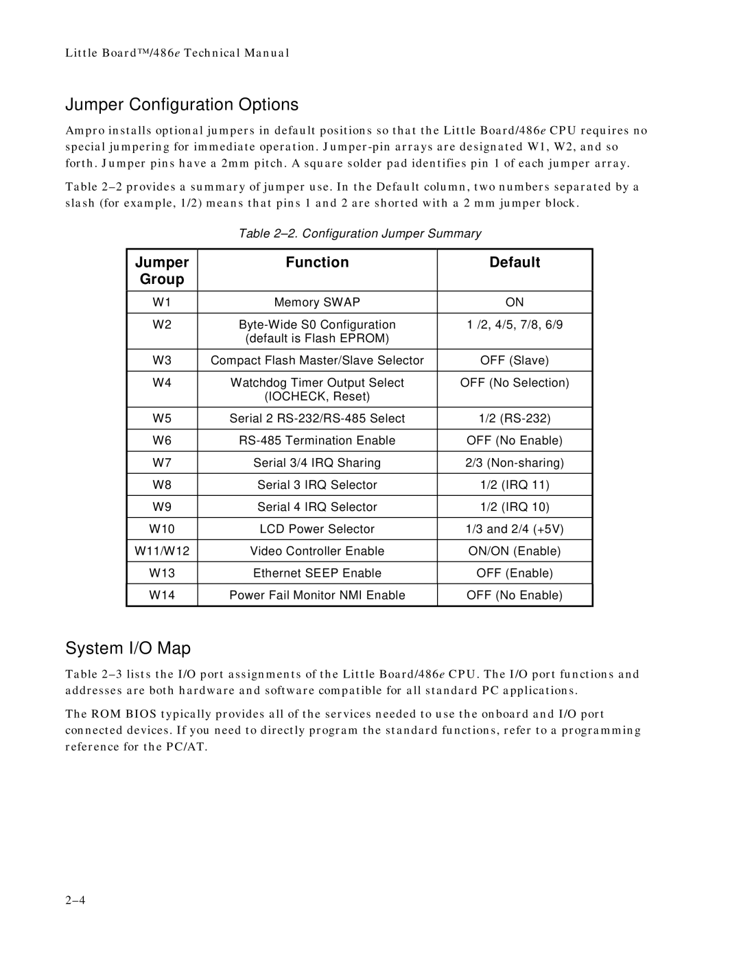
Ampro installs optional jumpers in default positions so that the Little Board/486e CPU requires no special jumpering for immediate operation.
Table
Table
Jumper
Group
Function
Default
W1 | Memory SWAP | ON |
|
|
|
W2 | 1 /2, 4/5, 7/8, 6/9 | |
| (default is Flash EPROM) |
|
|
|
|
W3 | Compact Flash Master/Slave Selector | OFF (Slave) |
|
|
|
W4 | Watchdog Timer Output Select | OFF (No Selection) |
| (IOCHECK, Reset) |
|
|
|
|
W5 | Serial 2 | 1/2 |
|
|
|
W6 | OFF (No Enable) | |
|
|
|
W7 | Serial 3/4 IRQ Sharing | 2/3 |
|
|
|
W8 | Serial 3 IRQ Selector | 1/2 (IRQ 11) |
|
|
|
W9 | Serial 4 IRQ Selector | 1/2 (IRQ 10) |
|
|
|
W10 | LCD Power Selector | 1/3 and 2/4 (+5V) |
|
|
|
W11/W12 | Video Controller Enable | ON/ON (Enable) |
|
|
|
W13 | Ethernet SEEP Enable | OFF (Enable) |
|
|
|
W14 | Power Fail Monitor NMI Enable | OFF (No Enable) |
|
|
|
System I/O Map
Table
The ROM BIOS typically provides all of the services needed to use the onboard and I/O port connected devices. If you need to directly program the standard functions, refer to a programming reference for the PC/AT.