Little Board™/486e Technical Manual
Table
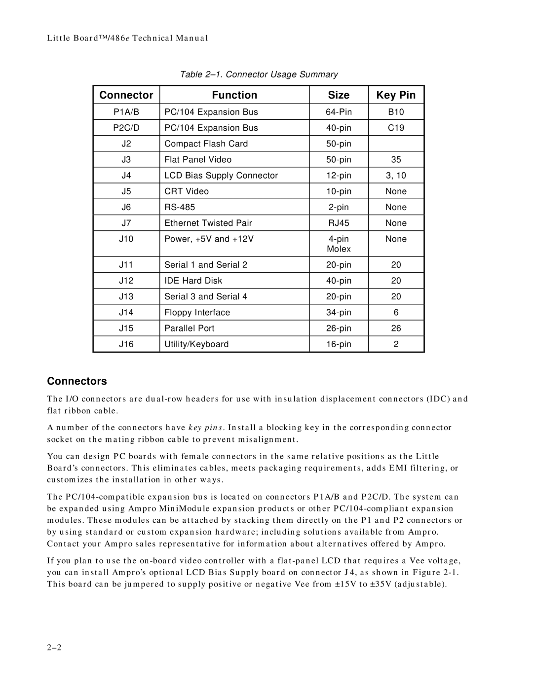
Connector | Function | Size | Key Pin |
|
|
|
|
P1A/B | PC/104 Expansion Bus | B10 | |
|
|
|
|
P2C/D | PC/104 Expansion Bus | C19 | |
|
|
|
|
J2 | Compact Flash Card |
| |
|
|
|
|
J3 | Flat Panel Video | 35 | |
|
|
|
|
J4 | LCD Bias Supply Connector | 3, 10 | |
|
|
|
|
J5 | CRT Video | None | |
|
|
|
|
J6 | None | ||
|
|
|
|
J7 | Ethernet Twisted Pair | RJ45 | None |
|
|
|
|
J10 | Power, +5V and +12V | None | |
|
| Molex |
|
|
|
|
|
J11 | Serial 1 and Serial 2 | 20 | |
|
|
|
|
J12 | IDE Hard Disk | 20 | |
|
|
|
|
J13 | Serial 3 and Serial 4 | 20 | |
|
|
|
|
J14 | Floppy Interface | 6 | |
|
|
|
|
J15 | Parallel Port | 26 | |
|
|
|
|
J16 | Utility/Keyboard | 2 | |
|
|
|
|
Connectors
The I/O connectors are
A number of the connectors have key pins. Install a blocking key in the corresponding connector socket on the mating ribbon cable to prevent misalignment.
You can design PC boards with female connectors in the same relative positions as the Little Board’s connectors. This eliminates cables, meets packaging requirements, adds EMI filtering, or customizes the installation in other ways.
The
If you plan to use the