Little Board™/486e Technical Manual
ROM-BIOS Installation of Parallel Ports
LPT1 is normally assigned to the primary parallel port by the BIOS, LPT2 to the secondary parallel port if present, and so on. However, the BIOS scans the standard addresses for parallel ports and assigns LPT designations in the order it finds them. Thus, a secondary parallel port (at address 278h) can be assigned LPT1 if there is no primary port.
Note
The scan order is 3BCh, 378h, 278h.
Standard and General Purpose I/O Operation
The parallel port can be used as a standard
!
!An LCD display
!Scan keyboards
!Sense switches
!Interface with optically isolated I/O modules
All data and interface control signals are
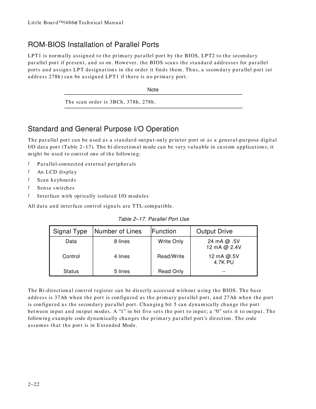
Table
Signal Type | Number of Lines | Function | Output Drive |
|
|
|
|
Data | 8 lines | Write Only | 24 mA @ .5V |
|
|
| 12 mA @ 2.4V |
Control | 4 lines | Read/Write | 12 mA @.5V |
|
|
| 4.7K PU |
Status | 5 lines | Read Only | |
|
|
|
|
The