Little Board™/486e Technical Manual
Floppy Interface Configuration
The floppy interface is configured using SETUP to set the number and type of floppy drives connected to the system. Refer to the SETUP section later in this chapter for details.
If the floppy interface is not used, disable it in SETUP. This frees its I/O addresses (3F0h - 3F7h), DMA2, and IRQ6 for use by other peripherals installed on the PC/104 bus.
Floppy Interface Connector (J14)
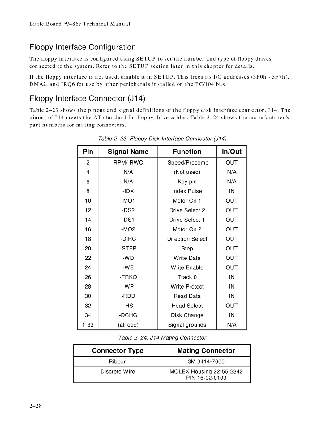
Table
Table
Pin | Signal Name | Function | In/Out |
|
|
|
|
2 | Speed/Precomp | OUT | |
4 | N/A | (Not used) | N/A |
6 | N/A | Key pin | N/A |
8 | Index Pulse | IN | |
10 | Motor On 1 | OUT | |
12 | Drive Select 2 | OUT | |
14 | Drive Select 1 | OUT | |
16 | Motor On 2 | OUT | |
18 | Direction Select | OUT | |
20 | Step | OUT | |
22 | Write Data | OUT | |
24 | Write Enable | OUT | |
26 | Track 0 | IN | |
28 | Write Protect | IN | |
30 | Read Data | IN | |
32 | Head Select | OUT | |
34 | Disk Change | IN | |
(all odd) | Signal grounds | N/A | |
|
|
|
|
Table
Connector Type
Mating Connector
Ribbon | 3M |
|
|
Discrete Wire | MOLEX Housing |
| PIN |
|
|