Appendix
Configurations of Terminals
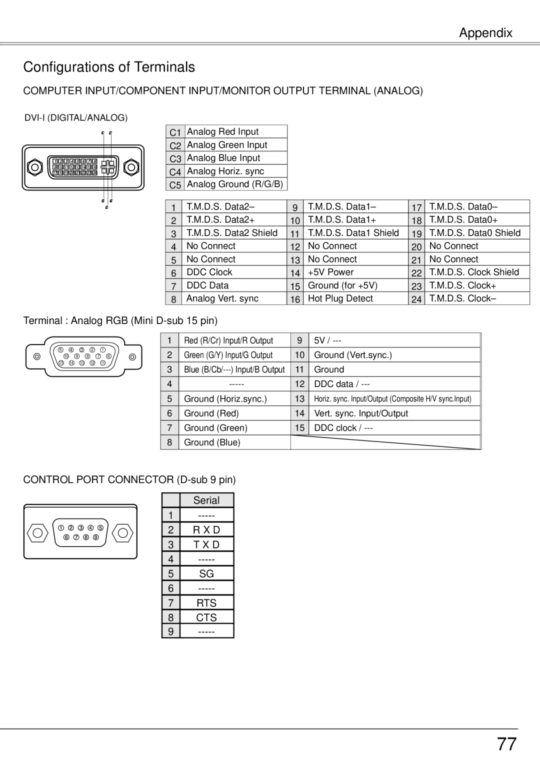
COMPUTER INPUT/COMPONENT INPUT/MONITOR OUTPUT TERMINAL (ANALOG)
C1 C2
![]() 1
1 ![]()
![]() 2
2 ![]()
![]() 3
3 ![]()
![]() 4
4 ![]()
![]() 5
5 ![]()
![]() 6
6 ![]()
![]() 7
7 ![]()
![]() 8
8 ![]()
![]() 9
9 ![]()
![]() 10
10![]()
![]() 11
11![]()
![]() 12
12![]()
![]() 13
13![]()
![]() 14
14![]()
![]() 15
15![]()
![]() 16
16![]()
![]() 17
17![]()
![]() 18
18![]()
![]() 19
19![]()
![]() 20
20![]()
![]() 21
21![]()
![]() 22
22![]()
![]() 23
23![]()
![]() 24
24![]()
C3 C4
C5
C1 | Analog Red Input |
C2 | Analog Green Input |
C3 | Analog Blue Input |
C4 | Analog Horiz. sync |
C5 | Analog Ground (R/G/B) |
1 | T.M.D.S. Data2– | 9 | T.M.D.S. Data1– | 17 | T.M.D.S. Data0– |
2 | T.M.D.S. Data2+ | 10 | T.M.D.S. Data1+ | 18 | T.M.D.S. Data0+ |
3 | T.M.D.S. Data2 Shield | 11 | T.M.D.S. Data1 Shield | 19 | T.M.D.S. Data0 Shield |
4 | No Connect | 12 | No Connect | 20 | No Connect |
5 | No Connect | 13 | No Connect | 21 | No Connect |
6 | DDC Clock | 14 | +5V Power | 22 | T.M.D.S. Clock Shield |
7 | DDC Data | 15 | Ground (for +5V) | 23 | T.M.D.S. Clock+ |
8 | Analog Vert. sync | 16 | Hot Plug Detect | 24 | T.M.D.S. Clock– |
Terminal : Analog RGB (Mini D-sub 15 pin)
5 4 3 2 1
10 9 8 7 6
15 14 13 12 11
1 | Red (R/Cr) Input/R Output | 9 | 5V / |
2 | Green (G/Y) Input/G Output | 10 | Ground (Vert.sync.) |
3 | Blue | 11 | Ground |
4 | 12 | DDC data / | |
5 | Ground (Horiz.sync.) | 13 | Horiz. sync. Input/Output (Composite H/V sync.Input) |
6 | Ground (Red) | 14 | Vert. sync. Input/Output |
7 | Ground (Green) | 15 | DDC clock / |
8 | Ground (Blue) |
|
|
CONTROL PORT CONNECTOR (D-sub 9 pin)
| Serial |
1 | |
2 | R X D |
3 | T X D |
4 | |
5 | SG |
6 | |
7 | RTS |
8 | CTS |
9 |
77