HARmonica Software Manual
Elmo Motion Control Inc
USA
HARSFEN0602ElmoHARmonicaSoftwareManual
HARSFEN0602ElmoHARmonicaSoftwareManual
Program execution
Preliminary
115
HARSFEN0602ElmoHARmonicaSoftwareManual
Language
100
HARSFEN0602ElmoHARmonicaSoftwareManual
About This Manual
Scope
Relevant documentation
Glossary
Harmonica
Related Software
Units
Position units
Can EDS
Internal Units and Conversions
Speed and acceleration units
Current and torque
Power DC voltage
Speed
Electrical angle
Peripherals
Digital output
A/D converter
Digital inputs
Communication With the Host
General RS232 Communications
1 RS232 Basics
Description
Errors and exceptions in RS232
Echo
Background Transmission
CANopen Communication
ElmoHARSFEN0602HARmonicaSoftwareManual Preliminarydraft
Interpreter Language
Command line
Expressions And Operators
Numbers
Mathematical And Logical Operators
Operator details
XOR
Addition
Subtraction
Multiplication
Division
Bitwise not
Bitwise or
Bitwise
Logical Equality
Logical Greater than or equal
Logical Less than
Logical
Logical or
Logical not
Unary Minus
Bitwise Left Shift and Right Shift operators
Mathematical functions
Assignment Expressions
Expressions
Simple Expressions
User variables
Built-in Function Calls
Time functions
Example ca1 =
User Function Calls
Comments
Harmonica User Programming Language
User Program Organization
Line Continuation
Common
Line and Expression Termination
General rules for operators
Limitations
Expressions And Operators Numbers
Expressions Simple Expressions
Syntax
System Commands
Built-in Function Calls
Program Flow Commands
Labels Entry points
For iteration
#@LABELNAME
XQ ##LOOP2
While iteration
Infiniteloop
Until iteration
While expression
Wait iteration
If condition
Switch selection
OFF
Syntax break
Break
Functions Function definition
Function is absent
Dummy variables
Count of output variables
Mean
Automatic variables
STD
Global variables
Jumps
##LABEL2
Functions and The Call Stack
##LABEL1
Return
Killing The Call Stack
Automatic subroutines List Of Automatic Routines
##STARTNEW
#@AUTOI1
Autoexec
Autoer
Autostop
Autobg
Automatic Routines Arbitration
Automatic Subroutine Mask
##LOOP
#@AUTOI3
#@TESTPARS
MI=MI8
Compilation Error List
Program Development and Execution
Editing a Program
Compilation
HARSFEN0602ElmoHARmonicaSoftwareManual
Asusid@elmo.co.il
Preliminarydraft
Preliminarydraft
Preliminarydraft
Preliminarydraft
Asusid@elmo.co.il
Downloading and Uploading a Program
#@AUTOEXEC
Examples
Assisting Commands For Down/Upload LPN command
Binary data
CP command
CC command
Downloading a Program DL command
Program downloading process
Uploading a Program LS command
Program execution
XQ##TASK1
Initiating a Program
Halting and resuming a program
Automatic program running with power up
DB command
Save to Flash
Clear user program from Flash
Machine status
Program status
DB##MS
DB##PSN
Setting and clearing break points
Continuation of the program
Single step
Run to Cursor
Step Out
Step Over
Step
Getting call stack
Setting stack
Getting stack entries
View of global variables
View of local variables
HARSFEN0602ElmoHARmonicaSoftwareManual
Call Stack During Function Call
Virtual Machines
Virtual Machine registers
Data types
Usrsubj
Op code structure and addressing modes
Short reference
REM
Rsltand
Rsltor
Not
Alphabetic reference
Bitwise and Operator
Purpose
Algorithm
CMP Compare
DIV Divide
Algorithm itr iterator
EOL End Of Line
Foritr for Loop Iteration
Freevac Free Virtual Machine
For Bitwise or Operator
Getcomm Get Command
JMP Jump
Jmpeol Jump
Jmplabel Jump to the label
JNZ Jump Not Zero
Jnzeol Jump Not Zero
Link
JZ Jump If Zero
Jzeol Jump If Zero
MLT Multiply
MOV Assignment Operator =
Not Bitwise not Operator
REM Reminder
Rslta Relational Operator
Rsltae Relational Operator =
Rsltand Logical and Operator
Rsltb Relational Operator
Rsltbe Relational Operator =
SP SP
Rslte Relational Operator ==
Rsltne Relational Operator !=
Setcomm Set Command
Rsltor Logical or Operator
SHR Shift Right
SHL Shift Left
Spadd
Syssubj Jump To System Subroutine
Unarynot Logical not Operator
OP2
Usrsubj jump To User Subroutine
Usrsubrt Return from user subroutine
XOR Bitwise XOR Operator
Recorder
BG,BT
ILN
RPN
Signal mapping
Signal Signal Name Command Length Description Type
Example The commands RV1=5RV2=1RC=3
Defining the set of recorded signals
Programming the length and the resolution
Trigger events and timing
Trigger delay
Slope and window trigger types
Preliminary
Definition
Uploading recorded data
100
Launching the recorder
101
Preliminary Draft
Byte Number Value Type
103
Commutation
General
Brush DC motors
Mechanical and electrical motion Figures are missing
104
Bldc commutation policy
Commutation sensors
Rotor Magnetic field sensors
106
Shaft Angle Sensors
Hall sensors parameterization
Detecting commutation errors loss of feedback
107
108
Encoder parameterization
Selecting the parameters
109
Commutation search General
Protections
110
Method limitation
111
Continuous Vs. Six-Steps commutation
112
Continuous commutation
113
Winding shapes
114
Loading the commutation table
115
Current controller
116
ID = I hθ + 90 + Ib hθ + 210 + Ic hθ +
117
Peak/Continuous current limit selection
Torque command filter
118
119
32768
120
PI current controller
121
Current amplifier protections
122
Unit Modes
Torque control Unit mode
123
124
Speed mode Unit mode
11.2.1The software speed command
Speed Profiling using JV, AC and DC
125
11.2.2The auxiliary speed command
126
RLS,FLS
127
Stop management
Stepper mode Unit mode
128
Dual feedback mode UM=4
129
Dual feedback mode UM=4
130
Single feedback mode UM=5
131
12.1.1Switching Between Motion Modes
132
Position reference generator
Software reference generator
12.1.2Comparison of the PT and the PVT interpolated modes
12.1.3The Idle Mode and Motion Status
133
134
12.1.4Point-To-Point PTP Basic Point-To-Point
135
Example
136
More Complicated PTP Motions
137
Example On-The-Fly Change of The Position Target
138
Jogging
Example Simple jogging
Example On the fly mode switching
139
140
141
Vt = 3at − t0 2 + 2bt − t0 + c
142
Ifference Counts Msec 500 1000 1500 2000 2500
143
144
QP… QV… QT…
145
Motion Management
PVT Decisions Flow Chart
146
147
Mode Termination
PVT Motion Using can
148
PVT Motion Programming Message
149
Underflow
150
Programming Sequence for The Auto Increment PVT Mode
Parameters of The PVT Motion Mode
151
152
Interpolation Mathematics
PT Motion What Is PT
153
PT Motion Programming The Basic Mode
154
Flow chart of the basic PT mode is depicted below
155
PT Motion Programming Message
PT Motion Using can
156
Programming Sequence for The Auto Increment PT Mode
157
Parameters of The PT Motion Mode
158
159
External Position Reference Generator
160
External position reference generator
161
Xt = 10000 ⋅ cos2πt + ct
162
Ecam
163
164
165
Dividing Ecam table into several logical portions
On the fly Ecam programming using can
166
Jump-Free Motor Starting Policy
167
Initializing the external reference parameters
168
Stop management 12.3.1General description
169
Stop Manager Internals
VHN,VLN
XM,YM
Right Limit Switch Marked as 3 in the Figure
Forward Limit Switch Marked as 4 in the Figure
170
Rate and Acceleration Marked as 5 in the Figure
171
Position output of the stop manager
Modulo counting Modulo Counting
172
Sensors, I/O, and Events
173
Digital Outputs
174
Events, and response methods
Manual inquiry
Periodical Inquiry
Homing and Capture What Is Homing?
175
Automatic routines
Real time Motion management, Homing, Capture, and Flag
Homing the auxiliary encoder
176
Homing Programming
177
On the fly position counter updates
13.5.5A homing with home switch and index example
Switches location
178
179
Example Double homing corrects backlash offsets
180
Capturing
Limits, Protections, Faults, and Diagnosis
181
VLN
182
Current limiting
183
Speed Protection
184
Position Protection
Enable switch
185
186
Limit switches
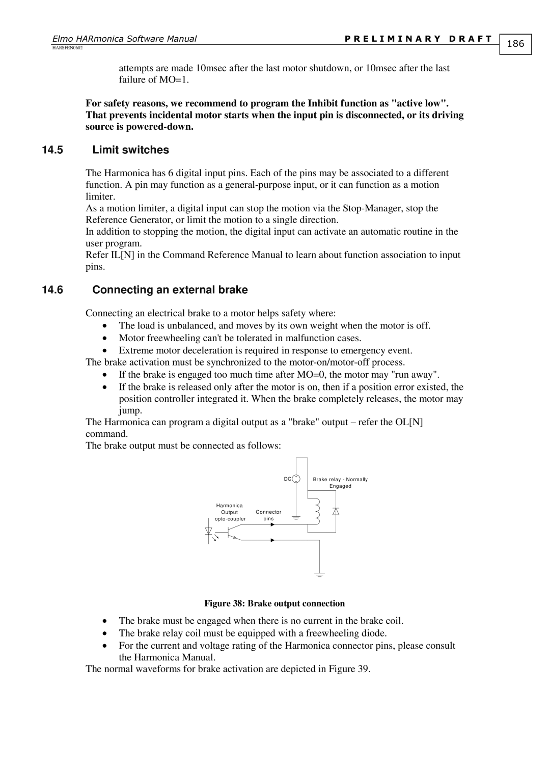
Connecting an external brake
187
When the motor fails to start
Motion faults
188
Diagnosis Monitoring motion faults
14.9.2Inconsistent setup data
189
Polling the amplifier status
14.9.3Device failures, and the CPU dump
Sensor faults Motor cannot move
190
Commutation error is static i.e. Does not change in time
191
Commutation is lost General
Reasons and effect of incorrect commutation
Detection of Commutation Feedback Fault
192
Commutation is drifting i.e Changes in time
Double sensor systems
KPN
193
Controller
Not found
Speed Control 15.2.1Block diagram
194
195
Parameters of the Speed Controller
Position Controller 15.3.1Block Diagram
196
197
Parameters of the Position Controller
198
High Order Filter Block Types
Double lead block Block type=12
Fist order block Block type=14
Scheduled Double lead block Block type=22
199
Second order block Block Type=15
An Example
200
User Interface
201
Gain-Scheduling Algorithm
202
Automatic Controller Gain-Scheduling
203
KP = SpeedKpTable k KI = SpeedKiTable k
Table of Contents TOC
204
Appendix a The Harmonica Flash Memory Organization
Main partitions
Contents of Text3
Contents of Text1
Contents of Text2
Contents of Text4-Text7
206
207
Contents of Text8
Contents of Text9
208
Autostop Autobg Autorls
Autoena AUTOI1
AUTOI5
209
Compilation Done Flag
210
TOC
Text Backup & Compiler data segment
Function Symbol Table
211
Virtual Machine Code Segment
Automatic Routines Table
Variable Symbol Table
212
213
Appendix B Harmonica Internals
Software Structure
17.1.1The Initialization block
214
Idle Loop
215
Idle loop
216
Converter
Converter Call
Algorithm
217
18.5 Examples
JP##LABEL
JS##LABEL Label
218