Functional description 33
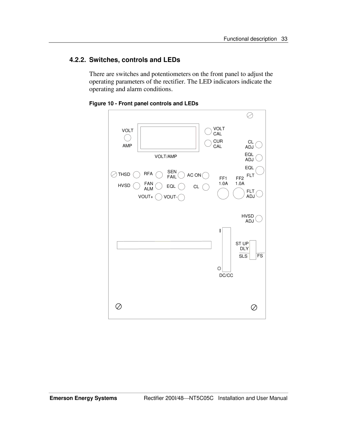
4.2.2.Switches, controls and LEDs
There are switches and potentiometers on the front panel to adjust the operating parameters of the rectifier. The LED indicators indicate the operating and alarm conditions.
Figure 10 - Front panel controls and LEDs
VOLT |
|
|
| VOLT |
|
|
|
|
| CAL |
|
| |
|
|
|
|
|
| |
AMP |
|
|
| CUR | CL |
|
|
|
| CAL | ADJ |
| |
|
| VOLT/AMP |
|
| EQL |
|
|
|
|
| ADJ |
| |
|
|
|
|
|
| |
| RFA | SEN |
|
| EQL |
|
THSD | AC ON |
| FF2 FLT |
| ||
FAIL | FF1 |
| ||||
|
|
| ||||
HVSD | FAN | EQL | CL | 1.0A | 1.0A |
|
ALM |
| FLT |
| |||
|
|
|
|
| ||
|
|
|
|
|
| |
| VOUT+ | VOUT- |
|
| ADJ |
|
|
|
|
|
| HVSD |
|
|
|
|
|
| ADJ |
|
|
|
|
|
| ST UP |
|
|
|
|
|
| DLY |
|
|
|
|
|
| SLS | FS |
|
|
|
| DC/CC |
|
|
Emerson Energy Systems | Rectifier 200I/48 NT5C05C Installation and User Manual |