Reference Manual
00809-0100-4696,Rev AA September
Rosemount 848L Discrete Logic
Temperature Transmitter with
Rosemount 848L
FOUNDATION Fieldbus
Table of Contents
SECTION 1 Introduction SECTION 2 Installation
SECTION 3 Configuration
Rosemount 848L
SECTION Operation and Maintenance APPENDIX A
Reference Data APPENDIX B Product Certifications
APPENDIX C Function Blocks
Rosemount 848L
APPENDIX D Logic Equation Syntax APPENDIX E
Motor Control
APPENDIX F Valve Control
Rosemount 848L
TOC-4
Rosemount 848L
Reference Manual
SAFETY MESSAGES Warnings
Section
Introduction
Rosemount 848L
OVERVIEW
Transmitter
Manual
Rosemount 848L
00809-0100-4696,Rev AA September
Rosemount 848L
Reference Manual
Rosemount 848L
Reference Manual
Installation
SAFETY MESSAGES Warnings MOUNTING
Section
Rosemount 848L
Mounting to a DIN Rail Without an Enclosure
Mounting to a Panel with a Junction Box
Rosemount 848L
Reference Manual
Mounting to a 2-InchPipe Stand
Rosemount 848L
Reference Manual
00809-0100-4696,Rev AA September
WIRING
Power Supply Connections
Rosemount 848L
Reference Manual
SWITCHES
Surges/Transients
GROUNDING
Rosemount 848L
00809-0100-4696,Rev AA September
Rosemount 848L
Reference Manual
I/O WIRING
DISCRETE INPUT WIRING CONFIGURATION
DISCRETE OUTPUT WIRING CONFIGURATION
Rosemount 848L
Reference Manual
TAGGING
Rosemount 848L
INSTALLATION Using Cable Glands
TRANSMITTER LABEL
Rosemount 848L
Reference Manual
Reference Manual
Using Conduit Entries
Rosemount 848L
Configuration
OVERVIEW SAFETY MESSAGES Warnings
Section
Rosemount 848L
Reference Manual
GENERAL BLOCK INFORMATION Modes
Rosemount 848L
Reference Manual
Link Active Scheduler Block Instantiation
Rosemount 848L
RESOURCE BLOCK FEATURES and FEATURES SEL
Capabilities
Rosemount 848L
Reference Manual
Reference Manual
MAX NOTIFY
Rosemount 848L
Reference Manual
PlantWeb Alarms
Rosemount 848L
00809-0100-4696,Rev AA September
Rosemount 848L
Reference Manual
00809-0100-4696,Rev AA September
Rosemount 848L
Reference Manual
Reference Manual
Alarms I/O TRANSDUCER BLOCK
Rosemount 848L
Reference Manual
LOGIC TRANSDUCER BLOCK
Rosemount 848L
Rosemount 848L
Reference Manual
00809-0100-4696,Rev AA September
Figure 3-1.848L Logic Transmitter Data Flow
00809-0100-4696,Rev AA September
Rosemount 848L
Reference Manual
00809-0100-4696,Rev AA September
Rosemount 848L
Reference Manual
00809-0100-4696,Rev AA September
Rosemount 848L
Reference Manual
00809-0100-4696,Rev AA September
Rosemount 848L
Reference Manual
00809-0100-4696,Rev AA September
Rosemount 848L
Reference Manual
00809-0100-4696,Rev AA September
Rosemount 848L
Reference Manual
00809-0100-4696,Rev AA September
Rosemount 848L
Reference Manual
00809-0100-4696,Rev AA September
Rosemount 848L
Reference Manual
Reference Manual
DISCRETE INPUT BLOCKS
Rosemount 848L
DISCRETE OUTPUT BLOCKS
MULTIPLE DISCRETE INPUT BLOCK
MULTIPLE DISCRETE OUTPUT BLOCK
Rosemount 848L
Rosemount 848L
Reference Manual
Section 4 Operation and Maintenance
FOUNDATION FIELDBUS INFORMATION
SAFETY MESSAGES Warnings
Rosemount 848L
MAINTENANCE
Communication/Power
Resetting the Configuration RESTART
Commissioning
TROUBLESHOOTING
I/O Transducer and Logic Block Troubleshooting
Resource Block
NAMUR Sensors
Rosemount 848L
Reference Manual
SPECIFICATIONS Functional Specifications
Appendix A
Reference Data
Rosemount 848L
00809-0100-4696,Rev AA September
Rosemount 848L
Reference Manual
00809-0100-4696,Rev AA September
Rosemount 848L
Reference Manual
Physical Specifications Function Blocks
Specification
Rosemount 848L
Reference Manual
Reference Manual
DIMENSIONAL DRAWINGS
Rosemount 848L
Figure A-3.Rosemount 848L Wiring Diagram
Rosemount 848L
Reference Manual
00809-0100-4696,Rev AA September
Reference Manual
ORDERING INFORMATION
Rosemount 848L
Rosemount 848L
Reference Manual
Appendix B Product Certifications
APPROVED MANUFACTURING LOCATIONS
EUROPEAN DIRECTIVE INFORMATION HAZARDOUS
LOCATIONS CERTIFICATES North American Approvals
Reference Manual
European Approvals
Rosemount 848L
Appendix C Function Blocks
RESOURCE BLOCK PARAMETERS
Rosemount 848L
Reference Manual
FREE SPACE
Rosemount 848L
Reference Manual
OUTPUT
Rosemount 848L
Reference Manual
Reference Manual
ADVISE ENABLE
Rosemount 848L
I/O TRANSDUCER PARAMETERS
Rosemount 848L
Reference Manual
00809-0100-4696,Rev AA September
TRANSDUCER TYPE
Rosemount 848L
Reference Manual
OUT 3 TAG
Rosemount 848L
Reference Manual
LOGIC TRANSDUCER PARAMETERS
Rosemount 848L
Reference Manual
00809-0100-4696,Rev AA September
Reference Manual
DISCRETE INPUT BLOCK
Rosemount 848L
Rosemount 848L
Reference Manual
00809-0100-4696,Rev AA September
Table C-4.Parameters
Reference Manual
DISCRETE OUTPUT BLOCK Supported Modes
Rosemount 848L
Reference Manual
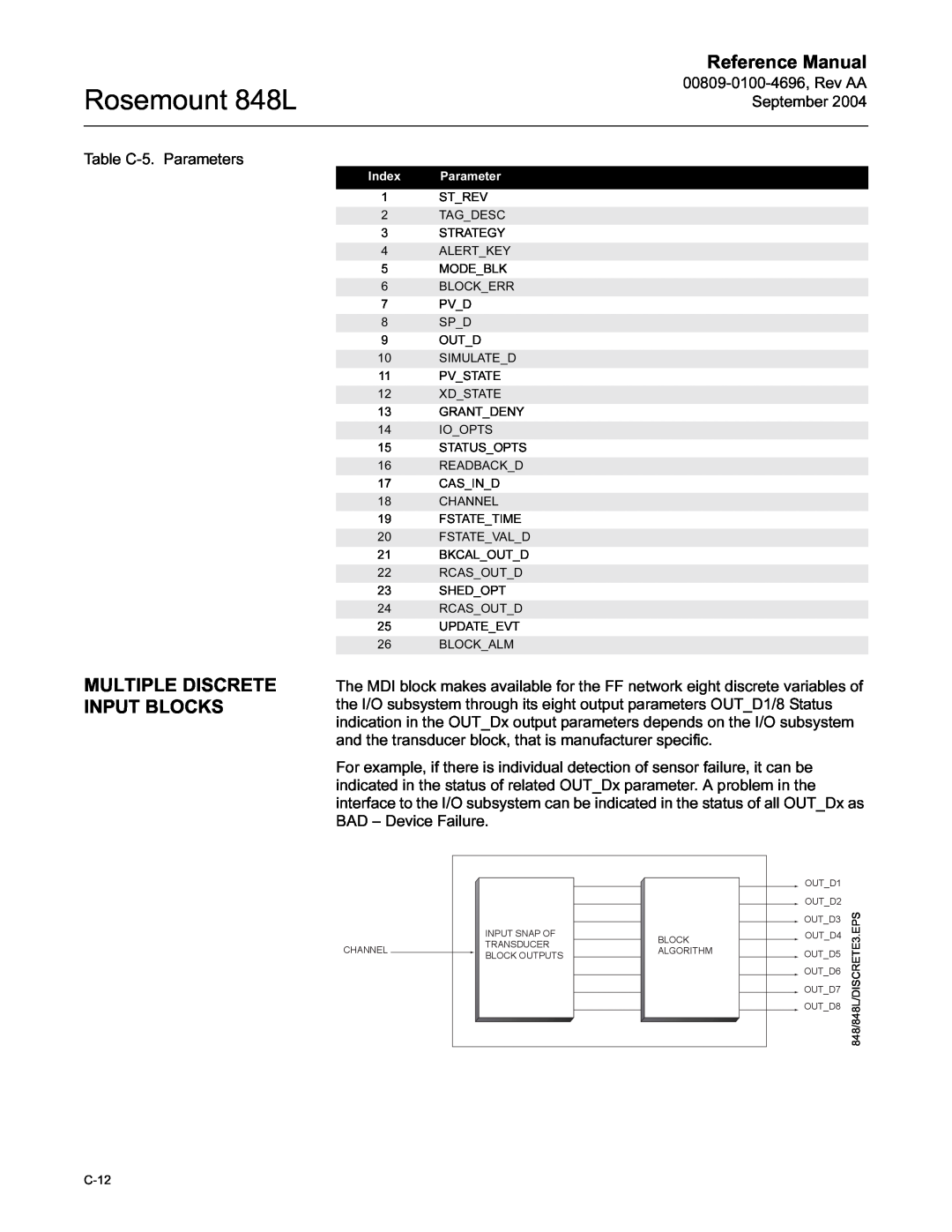
MULTIPLE DISCRETE INPUT BLOCKS
Rosemount 848L
Rosemount 848L
Reference Manual
MULTIPLE DISCRETE OUTPUT BLOCK
00809-0100-4696,Rev AA September
Rosemount 848L
Reference Manual
00809-0100-4696,Rev AA September
Table C-7.Parameters and
Reference Manual
Appendix D Logic Equation Syntax
Rosemount 848L
Rosemount 848L
Reference Manual
00809-0100-4696,Rev AA September
Table D-1.Supported Functions
PS channel number, divisor
Rosemount 848L
Reference Manual
ERROR HANDLING
Table D-2.Error Handling
Rosemount 848L
Reference Manual
Reference Manual
EXAMPLES
Rosemount 848L
Rosemount 848L
Reference Manual
Appendix E
Motor Control
INTRODUCTION TO MOTOR CONTROL
Rosemount 848L
Reference Manual
VARIATIONS ON MOTOR CONTROL
Rosemount 848L
00809-0100-4696,Rev AA September
Rosemount 848L
Reference Manual
Reference Manual
WRITING 848L EQUATIONS Basic Motor Control
Rosemount 848L
Reference Manual
Interlock Permissive Emergency Shutdown
Rosemount 848L
Reference Manual
Restart Delay
Rosemount 848L
Reference Manual
Maximum Restarts
Rosemount 848L
Reference Manual
Winding Temperature
Rosemount 848L
Reference Manual
Hand-Off-Auto
Rosemount 848L
Reference Manual
Intermediate Stop
Rosemount 848L
Reference Manual
Redundant Motors - Alternate Start
Rosemount 848L
Reference Manual
Redundant Motors - Timed Switch
Rosemount 848L
00809-0100-4696,Rev AA September
Rosemount 848L
Reference Manual
Reference Manual
Redundant Motors - Switch on Failure
Rosemount 848L
00809-0100-4696,Rev AA September
Rosemount 848L
Reference Manual
E-16
Rosemount 848L
Reference Manual
Appendix F
Valve Control
INTRODUCTION TO VALVE CONTROL
Rosemount 848L
Reference Manual
Alarms Variations on Valve Control
Rosemount 848L
Reference Manual
Boolean Expressions Basic Valve Control
Rosemount 848L
Open-Auto-Close Alarm Variations
Output Variations Output with Interlock
Rosemount 848L
Reference Manual
Reference Manual
Simple Valve Variations Permissive
Rosemount 848L
Reference Manual
Double Block and Bleed
Rosemount 848L
Reference Manual
Motorized Valve Heat Exchange Medium Selection
Rosemount 848L
Rosemount 848L
Reference Manual
Index
Rosemount 848L
Reference Manual
00809-0100-4696,Rev AA 9/17/04
00809-0100-4696,Rev AA 9/17/04
Rosemount 848L
Reference Manual
00809-0100-4696,Rev AA 9/17/04
Rosemount 848L
Reference Manual
Index-4
Rosemount 848L
Reference Manual
¢00809-0100-4697F¤
Reference Manual
