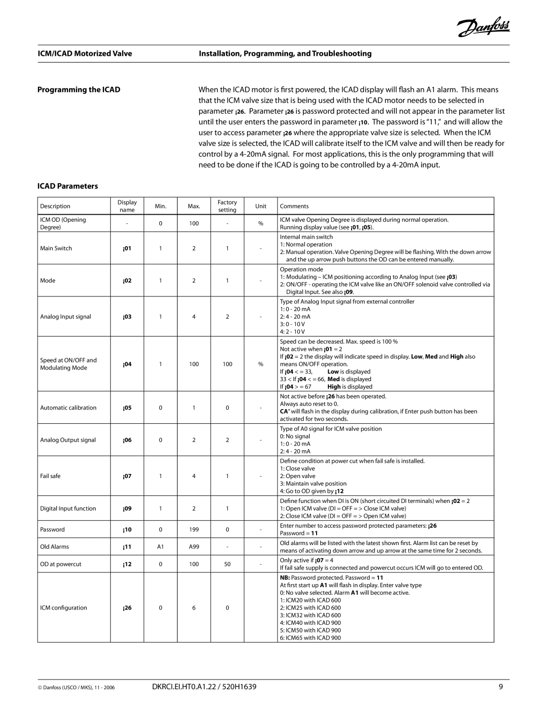
VSS, VSM, VSR specifications
Emerson VSM, VSR, and VSS are advanced technologies designed for process automation and control, often utilized in industrial applications. These systems are part of Emerson's broader portfolio of solutions aimed at enhancing operational efficiency, safety, and reliability.The Emerson VSM, or Valve Signature Management, focuses on the digital management of valves within a system. One of its main features includes advanced diagnostics that monitor the health and performance of control valves. This technology allows for predictive maintenance, ensuring that valves operate at peak efficiency and reducing the risk of unexpected failures. The VSM utilizes a combination of smart sensors and actuators to gather data, enabling real-time analytics that can enhance decision-making and operational strategies.
On the other hand, VSR, or Valve Status Reporting, enhances visibility into the operational state of valves in real time. This system provides operators with critical updates and alerts related to valve conditions, significantly reducing response times to potential issues. The VSR technology integrates seamlessly with existing control systems, allowing for easier implementation and minimal disruption to ongoing operations. The reporting capabilities feature user-friendly dashboards that present complex data in a straightforward manner, empowering operators to make informed decisions quickly.
The Emerson VSS, or Valve Service Solutions, complements the VSM and VSR by focusing on the maintenance and support of valve systems. This offering includes comprehensive service packages that range from routine maintenance to advanced troubleshooting and repair. The VSS is designed to improve the lifespan of valves through proactive service, ensuring reliability and minimal downtime. Emerson’s trained technicians leverage predictive analytics derived from VSM and VSR data, allowing for timely intervention before issues escalate.
In summary, Emerson’s VSM, VSR, and VSS technologies work together to create a robust ecosystem for valve management in industrial settings. The combination of advanced diagnostics, real-time reporting, and comprehensive service solutions provides operators with a powerful toolkit aimed at optimizing performance and ensuring operational reliability. With these technologies, companies can embrace digital transformation, reduce operational risks, and improve overall process efficiency, leading to a safer and more productive environment. Each component plays a crucial role in empowering industries to meet the challenges of modern automation and maintain competitive advantages in their respective markets.

