Operation

OIL SYSTEM

A. Oil Charge

Charge the oil separator with the proper quantity of lubricating oil (see Table 2 in the Installation Section).

CAUTION

It is imperative you charge the oil into the receiver/ separator prior to energizing the control panel to prevent burning out the immersion heater in the separator/receiver.

During operation, maintain the separator oil level in the normal operating range between the two bullseye sight glasses. If the oil level is visible only in the lowest sight glass, add oil to the operating compressor through the connection located at the compressor suction inlet. Pump oil into the compres- sor until the oil level in the separator is between the two bullseye sight glasses. Watch this level carefully to maintain proper operation. Never allow the oil to reach a level higher than indicated on the highest sight glass, since this may impair the operation and efficiency of the oil separator portion of this combi- nation vessel.

B. Oil Separator

The refrigerant-oil mixture is led into the first part of oil separator. There, the first step of oil separa- tion is performed by a combined agglomerator/ demister. At the same time, these part of the oil separator serves as oil collector.

In the second part of the oil separator, the fine separation of the aerosol oil portion from the re- frigerant is performed by means of replaceable fine oil separation cartridges. The oil separated in the fine section of the oil separator is returned to the compressor via an additional injection orifice.

C. Oil Filter

Change the oil filter after the first 200 hours of opera- tion, as noted on the hour meter. Thereafter, replace the filter every six months, or when the oil pressure drop through the filter reaches 45 psi, whichever oc- curs first. The pressure drop across the filter is read on the microprocessor panel. Check the pressure drop and record it daily.

To prepare for the removal of the filter, shut down the compressor. Isolate the filter housing appropri- ately. If unit is equipped with duplex filter housings the unit does not have to be shut down, however the filter to be serviced must be isolated before the tank can be opened.

1.Filter Removal, VSS Units using Vilter Part Number 1833C oil filter elements.

Release the pressure in the oil filter housing by opening the bleed valves at the stop valve in the block and bleed assembly, or at the bleed valve for the oil filter housing. Be sure to follow all Local, State, and Federal ordinances regarding the recovery of refrigerants.

Drain the filter housing in to an appropriate container and dispose of the oil in a appropriate manner following all Local, State and Federal ordinances regarding the disposal of used oil.

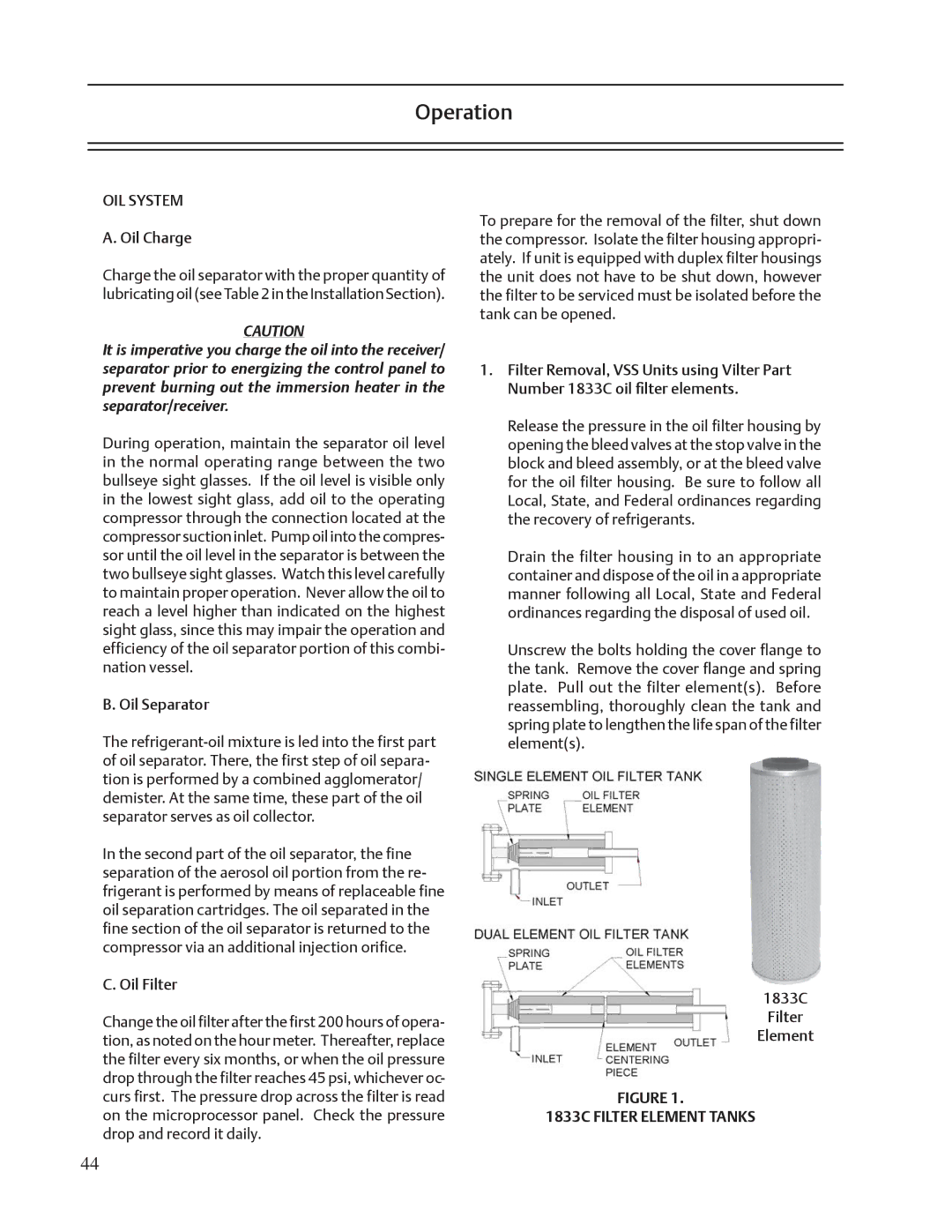
Unscrew the bolts holding the cover flange to the tank. Remove the cover flange and spring plate. Pull out the filter element(s). Before reassembling, thoroughly clean the tank and spring plate to lengthen the life span of the filter element(s).

1833C

Filter

Element

FIGURE 1.

1833C FILTER ELEMENT TANKS

44

Page 44
Image 44
Emerson VSS, VSR, VSM service manual Operation, OIL System

VSS, VSM, VSR specifications

Emerson VSM, VSR, and VSS are advanced technologies designed for process automation and control, often utilized in industrial applications. These systems are part of Emerson's broader portfolio of solutions aimed at enhancing operational efficiency, safety, and reliability.

The Emerson VSM, or Valve Signature Management, focuses on the digital management of valves within a system. One of its main features includes advanced diagnostics that monitor the health and performance of control valves. This technology allows for predictive maintenance, ensuring that valves operate at peak efficiency and reducing the risk of unexpected failures. The VSM utilizes a combination of smart sensors and actuators to gather data, enabling real-time analytics that can enhance decision-making and operational strategies.

On the other hand, VSR, or Valve Status Reporting, enhances visibility into the operational state of valves in real time. This system provides operators with critical updates and alerts related to valve conditions, significantly reducing response times to potential issues. The VSR technology integrates seamlessly with existing control systems, allowing for easier implementation and minimal disruption to ongoing operations. The reporting capabilities feature user-friendly dashboards that present complex data in a straightforward manner, empowering operators to make informed decisions quickly.

The Emerson VSS, or Valve Service Solutions, complements the VSM and VSR by focusing on the maintenance and support of valve systems. This offering includes comprehensive service packages that range from routine maintenance to advanced troubleshooting and repair. The VSS is designed to improve the lifespan of valves through proactive service, ensuring reliability and minimal downtime. Emerson’s trained technicians leverage predictive analytics derived from VSM and VSR data, allowing for timely intervention before issues escalate.

In summary, Emerson’s VSM, VSR, and VSS technologies work together to create a robust ecosystem for valve management in industrial settings. The combination of advanced diagnostics, real-time reporting, and comprehensive service solutions provides operators with a powerful toolkit aimed at optimizing performance and ensuring operational reliability. With these technologies, companies can embrace digital transformation, reduce operational risks, and improve overall process efficiency, leading to a safer and more productive environment. Each component plays a crucial role in empowering industries to meet the challenges of modern automation and maintain competitive advantages in their respective markets.