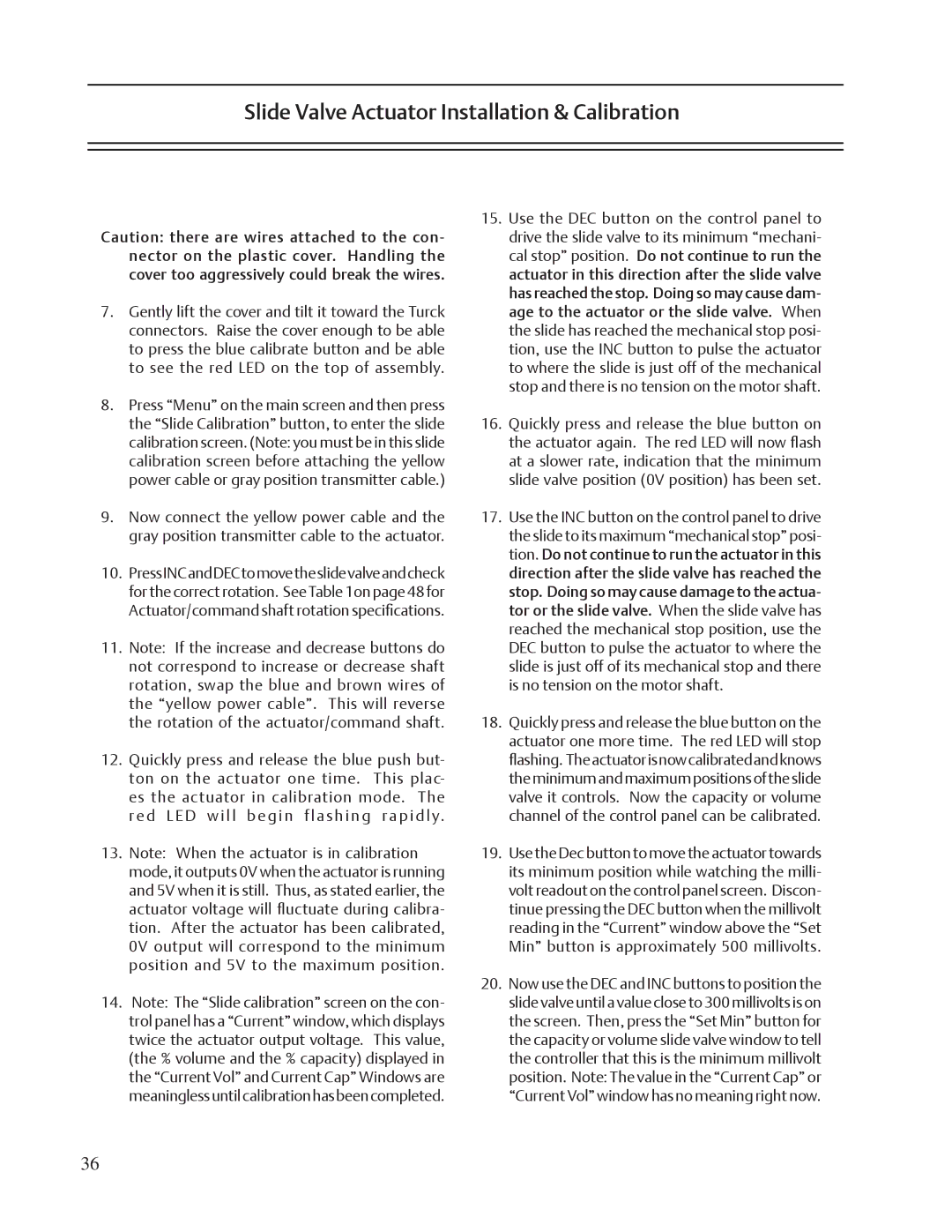
Slide Valve Actuator Installation & Calibration

Caution: there are wires attached to the con- nector on the plastic cover. Handling the cover too aggressively could break the wires.

7.Gently lift the cover and tilt it toward the Turck connectors. Raise the cover enough to be able to press the blue calibrate button and be able to see the red LED on the top of assembly.

8.Press “Menu” on the main screen and then press the “Slide Calibration” button, to enter the slide calibration screen. (Note: you must be in this slide calibration screen before attaching the yellow power cable or gray position transmitter cable.)

9.Now connect the yellow power cable and the gray position transmitter cable to the actuator.

10.PressINCandDECtomovetheslidevalveandcheck for the correct rotation. See Table 1on page 48 for Actuator/command shaft rotation specifications.

11.Note: If the increase and decrease buttons do not correspond to increase or decrease shaft rotation, swap the blue and brown wires of the “yellow power cable”. This will reverse the rotation of the actuator/command shaft.

12.Quickly press and release the blue push but- ton on the actuator one time. This plac- es the actuator in calibration mode. The red LED will begin flashing rapidly.

13.Note: When the actuator is in calibration mode, it outputs 0V when the actuator is running and 5V when it is still. Thus, as stated earlier, the actuator voltage will fluctuate during calibra- tion. After the actuator has been calibrated, 0V output will correspond to the minimum position and 5V to the maximum position.

14.Note: The “Slide calibration” screen on the con- trol panel has a “Current” window, which displays twice the actuator output voltage. This value, (the % volume and the % capacity) displayed in the “Current Vol” and Current Cap” Windows are meaninglessuntilcalibrationhasbeencompleted.

15.Use the DEC button on the control panel to drive the slide valve to its minimum “mechani- cal stop” position. Do not continue to run the actuator in this direction after the slide valve has reached the stop. Doing so may cause dam- age to the actuator or the slide valve. When the slide has reached the mechanical stop posi- tion, use the INC button to pulse the actuator to where the slide is just off of the mechanical stop and there is no tension on the motor shaft.

16.Quickly press and release the blue button on the actuator again. The red LED will now flash at a slower rate, indication that the minimum slide valve position (0V position) has been set.

17.Use the INC button on the control panel to drive the slide to its maximum “mechanical stop” posi- tion. Do not continue to run the actuator in this direction after the slide valve has reached the stop. Doing so may cause damage to the actua- tor or the slide valve. When the slide valve has reached the mechanical stop position, use the DEC button to pulse the actuator to where the slide is just off of its mechanical stop and there is no tension on the motor shaft.

18.Quickly press and release the blue button on the actuator one more time. The red LED will stop flashing. Theactuatorisnowcalibratedandknows theminimumandmaximumpositionsoftheslide valve it controls. Now the capacity or volume channel of the control panel can be calibrated.

19.Use the Dec button to move the actuator towards its minimum position while watching the milli- volt readout on the control panel screen. Discon- tinue pressing the DEC button when the millivolt reading in the “Current” window above the “Set Min” button is approximately 500 millivolts.

20.Now use the DEC and INC buttons to position the slide valve until a value close to 300 millivolts is on the screen. Then, press the “Set Min” button for the capacity or volume slide valve window to tell the controller that this is the minimum millivolt position. Note: The value in the “Current Cap” or “Current Vol” window has no meaning right now.

36

Page 36
Image 36
Emerson VSR, VSM, VSS service manual Slide Valve Actuator Installation & Calibration

VSS, VSM, VSR specifications

Emerson VSM, VSR, and VSS are advanced technologies designed for process automation and control, often utilized in industrial applications. These systems are part of Emerson's broader portfolio of solutions aimed at enhancing operational efficiency, safety, and reliability.

The Emerson VSM, or Valve Signature Management, focuses on the digital management of valves within a system. One of its main features includes advanced diagnostics that monitor the health and performance of control valves. This technology allows for predictive maintenance, ensuring that valves operate at peak efficiency and reducing the risk of unexpected failures. The VSM utilizes a combination of smart sensors and actuators to gather data, enabling real-time analytics that can enhance decision-making and operational strategies.

On the other hand, VSR, or Valve Status Reporting, enhances visibility into the operational state of valves in real time. This system provides operators with critical updates and alerts related to valve conditions, significantly reducing response times to potential issues. The VSR technology integrates seamlessly with existing control systems, allowing for easier implementation and minimal disruption to ongoing operations. The reporting capabilities feature user-friendly dashboards that present complex data in a straightforward manner, empowering operators to make informed decisions quickly.

The Emerson VSS, or Valve Service Solutions, complements the VSM and VSR by focusing on the maintenance and support of valve systems. This offering includes comprehensive service packages that range from routine maintenance to advanced troubleshooting and repair. The VSS is designed to improve the lifespan of valves through proactive service, ensuring reliability and minimal downtime. Emerson’s trained technicians leverage predictive analytics derived from VSM and VSR data, allowing for timely intervention before issues escalate.

In summary, Emerson’s VSM, VSR, and VSS technologies work together to create a robust ecosystem for valve management in industrial settings. The combination of advanced diagnostics, real-time reporting, and comprehensive service solutions provides operators with a powerful toolkit aimed at optimizing performance and ensuring operational reliability. With these technologies, companies can embrace digital transformation, reduce operational risks, and improve overall process efficiency, leading to a safer and more productive environment. Each component plays a crucial role in empowering industries to meet the challenges of modern automation and maintain competitive advantages in their respective markets.