Installation

To begin the second evacuation, allow the pump to operate and reduce the pressure again to within 50 to 1000 microns. After this reading is reached, allow the pump to operate 2 or 3 hours. Stop the pump and let the system stand with this vacuum. Again using dry nitrogen, raise the system pressure to zero.

For the third evacuation, follow the previous procedure with the pump operating until system pressure is reduced below the 1000 micron level. Run the pump an additional 6 hours and hold the system for approximately 12 hours at low pres- sure. After this, again break the vacuum with dry nitrogen and allow the pressure in the system to rise slightly above zero pounds (psig). Install new drier cartridges and moisture indicators. Charge the system once more below the 1000 micron level and use the refrigerant designed for the system.

When properly evacuating the system as outlined above, the system is dry, oxygen-free and free of non-condensables. The piping should not be in- sulated before the evacuation process is started. If moisture is in the system before evacuating, it condenses in low places and freezes. If this hap- pens, it can be removed by gently heating the trap farthest away from the vacuum pump. This causes the ice to melt and water to boil. Water va- por collects in the next trap towards the vacuum pump. This process should be repeated until all pockets of water have been boiled off, and the vacuum pump has had a chance to remove all the water vapor from the system.

VI.

UNIT OIL CHARGING

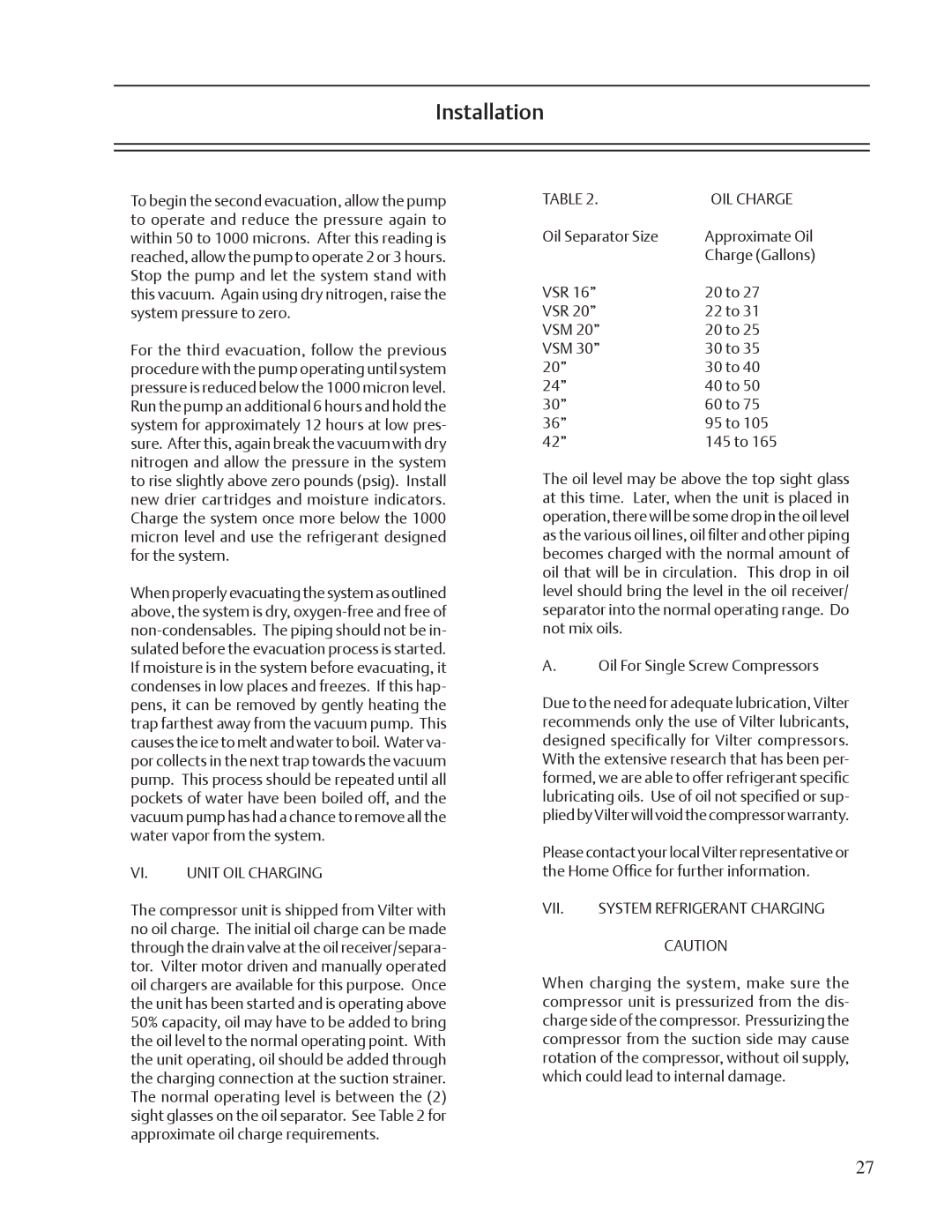
The compressor unit is shipped from Vilter with no oil charge. The initial oil charge can be made through the drain valve at the oil receiver/separa- tor. Vilter motor driven and manually operated oil chargers are available for this purpose. Once the unit has been started and is operating above 50% capacity, oil may have to be added to bring the oil level to the normal operating point. With the unit operating, oil should be added through the charging connection at the suction strainer. The normal operating level is between the (2) sight glasses on the oil separator. See Table 2 for approximate oil charge requirements.

TABLE 2.

OIL CHARGE

Oil Separator Size

Approximate Oil


Charge (Gallons)

VSR 16”

20 to 27

VSR 20”

22 to 31

VSM 20”

20 to 25

VSM 30”

30 to 35

20”

30 to 40

24”

40 to 50

30”

60 to 75

36”

95 to 105

42”

145 to 165

The oil level may be above the top sight glass at this time. Later, when the unit is placed in operation, there will be some drop in the oil level as the various oil lines, oil filter and other piping becomes charged with the normal amount of oil that will be in circulation. This drop in oil level should bring the level in the oil receiver/ separator into the normal operating range. Do not mix oils.

A.Oil For Single Screw Compressors

Due to the need for adequate lubrication, Vilter recommends only the use of Vilter lubricants, designed specifically for Vilter compressors. With the extensive research that has been per- formed, we are able to offer refrigerant specific lubricating oils. Use of oil not specified or sup- plied by Vilter will void the compressor warranty.

Please contact your local Vilter representative or the Home Office for further information.

VII.

SYSTEM REFRIGERANT CHARGING

CAUTION

When charging the system, make sure the compressor unit is pressurized from the dis- charge side of the compressor. Pressurizing the compressor from the suction side may cause rotation of the compressor, without oil supply, which could lead to internal damage.

27

Page 27
Image 27
Emerson VSR, VSM, VSS service manual OIL Charge, Vii

VSS, VSM, VSR specifications

Emerson VSM, VSR, and VSS are advanced technologies designed for process automation and control, often utilized in industrial applications. These systems are part of Emerson's broader portfolio of solutions aimed at enhancing operational efficiency, safety, and reliability.

The Emerson VSM, or Valve Signature Management, focuses on the digital management of valves within a system. One of its main features includes advanced diagnostics that monitor the health and performance of control valves. This technology allows for predictive maintenance, ensuring that valves operate at peak efficiency and reducing the risk of unexpected failures. The VSM utilizes a combination of smart sensors and actuators to gather data, enabling real-time analytics that can enhance decision-making and operational strategies.

On the other hand, VSR, or Valve Status Reporting, enhances visibility into the operational state of valves in real time. This system provides operators with critical updates and alerts related to valve conditions, significantly reducing response times to potential issues. The VSR technology integrates seamlessly with existing control systems, allowing for easier implementation and minimal disruption to ongoing operations. The reporting capabilities feature user-friendly dashboards that present complex data in a straightforward manner, empowering operators to make informed decisions quickly.

The Emerson VSS, or Valve Service Solutions, complements the VSM and VSR by focusing on the maintenance and support of valve systems. This offering includes comprehensive service packages that range from routine maintenance to advanced troubleshooting and repair. The VSS is designed to improve the lifespan of valves through proactive service, ensuring reliability and minimal downtime. Emerson’s trained technicians leverage predictive analytics derived from VSM and VSR data, allowing for timely intervention before issues escalate.

In summary, Emerson’s VSM, VSR, and VSS technologies work together to create a robust ecosystem for valve management in industrial settings. The combination of advanced diagnostics, real-time reporting, and comprehensive service solutions provides operators with a powerful toolkit aimed at optimizing performance and ensuring operational reliability. With these technologies, companies can embrace digital transformation, reduce operational risks, and improve overall process efficiency, leading to a safer and more productive environment. Each component plays a crucial role in empowering industries to meet the challenges of modern automation and maintain competitive advantages in their respective markets.