Connecting
Note: The
•
•
•If the stack is in a configuration where the adjacent switches are two far apart for the short cables, the long cable can be used for the connections.
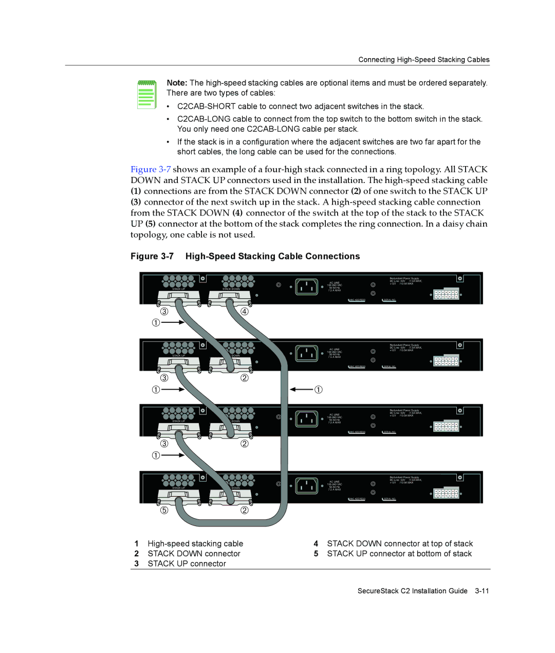
Figure 3‐7 shows an example of a four‐high stack connected in a ring topology. All STACK DOWN and STACK UP connectors used in the installation. The high‐speed stacking cable
(1)connections are from the STACK DOWN connector (2) of one switch to the STACK UP
(3)connector of the next switch up in the stack. A high‐speed stacking cable connection from the STACK DOWN (4) connector of the switch at the top of the stack to the STACK UP (5) connector at the bottom of the stack completes the ring connection. In a daisy chain topology, one cable is not used.
Figure 3-7 High-Speed Stacking Cable Connections
| STACK UP | STACK DOWN |
| |||
|
|
|
|
|
|
|
|
|
|
|
|
|
|
 |  | à |
À |
|
|
AC LINE
7.5 A MAX
Redundant Power Supply
DC Line
+12V /10.5A MAX
MAC ADDRESS | SERIAL NO. |
STACK UP | STACK DOWN |
AC LINE
7.5 A MAX
Redundant Power Supply
DC Line
+12V /10.5A MAX
MAC ADDRESS | SERIAL NO. |
 |  | Á |
À |
| À |
| STACK UP | STACK DOWN |
| |||
|
|
|
|
|
|
|
|
|
|
|
|
|
|
 |  | Á |
À |
|
|
AC LINE
7.5 A MAX
Redundant Power Supply
DC Line
+12V /10.5A MAX
MAC ADDRESS | SERIAL NO. |
| STACK UP | STACK DOWN |
| |||
|
|
|
|
|
|
|
|
|
|
|
|
|
|
![]() Ä Ä
Ä Ä ![]() Á
Á![]()
AC LINE
7.5 A MAX
Redundant Power Supply
DC Line
+12V /10.5A MAX
MAC ADDRESS | SERIAL NO. |
1 | 4 | STACK DOWN connector at top of stack | |
2 | STACK DOWN connector | 5 | STACK UP connector at bottom of stack |
3STACK UP connector
SecureStack C2 Installation Guide