Connecting to the Network
When these parameters are set, the Startup screen will display. If the switches are in a stacked configuration, proceed to “Connecting to the Network” on page 3‐21.
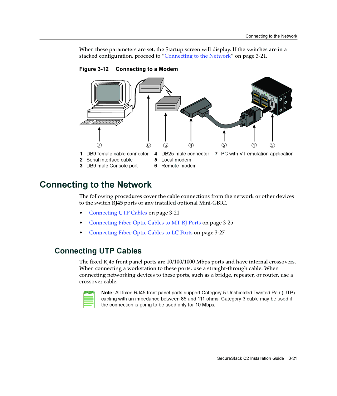
Figure 3-12 Connecting to a Modem
45 ![]() 46
46
47 ![]() 48
48
Console
|
|
|
|
|
|
|
|
|
|
|
|
|
|
|
|
|
|
|
|
|
|
|
|
|
|
|
|
|
|
|
|
|
|
|
|
|
|
|
|
|
|
|
|
|
|
|
|
|
|
|
|
|
|
|
|
|
|
|
|
|
|
|
|
|
|
|
|
|
|
|
|
|
|
|
|
|
|
|
|
|
|
|
|
|
|
|
|
|
|
|
|
|
|
|
|
|
|
|
|
|
|
|
|
|
|
|
|
|
|
|
|
|
|
|
|
|
|
|
|
|
|
|
|
|
|
|
|
|
|
|
|
|
|
|
|
|
|
|
|
|
| Æ |
|
| Å |
| Ä | Ã | Á | À | Â | ||||||||
1 | DB9 female cable connector | 4 | DB25 male connector | 7 PC with VT emulation application | |||||||||||||||
2 | Serial interface cable |
| 5 | Local modem |
|
|
|
|
|
| |||||||||
3 | DB9 male Console port |
| 6 | Remote modem |
|
|
|
|
|
| |||||||||
Connecting to the Network
The following procedures cover the cable connections from the network or other devices to the switch RJ45 ports or any installed optional Mini‐GBIC.
•Connecting UTP Cables on page 3‐21
•Connecting Fiber‐Optic Cables to MT‐RJ Ports on page 3‐25
•Connecting Fiber‐Optic Cables to LC Ports on page 3‐27
Connecting UTP Cables
The fixed RJ45 front panel ports are 10/100/1000 Mbps ports and have internal crossovers. When connecting a workstation to these ports, use a straight‐through cable. When connecting networking devices to these ports, such as a bridge, repeater, or router, use a crossover cable.
Note: All fixed RJ45 front panel ports support Category 5 Unshielded Twisted Pair (UTP) cabling with an impedance between 85 and 111 ohms. Category 3 cable may be used if the connection is going to be used only for 10 Mbps.
SecureStack C2 Installation Guide