User Guide
Safety Instructions English
Safety Instructions
Guide on the Extron website
FCC Class a Notice
Software Commands
Specifications Availability
Conventions Used in this Guide
Notifications
Contents
SIS Programming and Control
About the DMP 64 Digital Matrix Processor
About This Guide
Features
DMP 64 Introduction
Extron DMP
DMP 64 Application Diagram
DMP 64 Rear Panel
Mounting the DMP
Power Supply Wiring
Balanced or Unbalanced Mic and Line Input Wiring
Digital I/O Wiring
USB Configuration Port Front Panel
DMP 64 Operation
Hardware Operation
DMP 64 Front Panel
Front Panel Operation
Firmware Updates
Power Cycle
Rear Panel Operation
Hardware Reset Modes
Reset Actuator and LED Indicator
Mode 1 Firmware reset
Mode 1 will
Mode 4 will
Mode 4 IP Address reset
Mode 5 Factory default reset
Default reset state of the device is
DMP 64 has the following connection options
Software Control
Install the software as follows
Installing the DSP Configurator Program
Embedded Web Pages
Windows-based Program Control
DVD Software Menu
USB Installer Splash Screen
Install the USB Driver
Using the Program
DSP Configurator Program Basics
Starting the Program
C d e f g
Cut, Copy, or Paste Functions
Navigation
Keyboard Navigation
Mouse Navigation
DMP 64 Software Control
File
DSP Configurator Toolbar Menus
Edit
Tools
View
DMP 64 Software Control
Help selection
Window Menu
Mode Buttons
Presets Drop-down
Backup
Audio Level, Mix-point, Processing Blocks, and Signal Chains
Processor Blocks
Level Control Blocks
Sample Processor Dialog Box
Gain Control Gain
Mic/Line Input Signal Controls
Insert Filter Menu
Filter Filt
Filter Block Dialog Box
Filter Dialog Box, Filters Added
Type Frequency Parameter
Filter Parameter Settings Range
High Pass Filter Response Curve
High Pass
Low Pass Filter Response Curve
Low Pass
Bass and Treble Shelving
Bass and Treble Shelving
Parametric Filter Dialog Box, 1000 Hz
Parametric Equalizer
Parametric Filter at 1000 Hz, Q
All Parametric Filters Active
Feedback Suppressor
Feedback Suppressor FBS
Value Application
FBS Settings
FBS Dynamic Filters Tab
FBS Dynamic Filters
FBS Fixed Filters
Fixed Filter Parameter Settings Range Default Setting
Compressor
Dynamics DYN
Limiter
Gate
Automatic Gain Control AGC
Compressor
Limiter
Noise Gate
Method Time Feet Meters
Delay DLY
Ducking Duck
Ducker Configuration Dialog
Current source indicator
Ducking Configuration
Enable mic/line source checkbox
Settings
By dB Target gain reduction amount
Priority
Mix Status for virtual returns
Ducking Priority
Ducking and Priority Ducking
Ducker Tutorials
To set a ducking source
To set an additional ducking source
Pre-mixer Gain Gain
Loudness Loud
Line Output Channels
Calibrating Loudness
Setting Loudness By Ear
Alternate method to calibrate loudness
Filter Block Filt
Delay Block DLY
Dynamics Block DYN
Volume Control VOL
Gain Gain
Virtual Bus Returns
Primary Mix Matrix outlined in red
Primary Mix Matrix
Mix-point Behavior
DMP 64 Software Control
Input 1 to Output
Mix-point Examples
All Inputs to Output
Input 1 to All Outputs
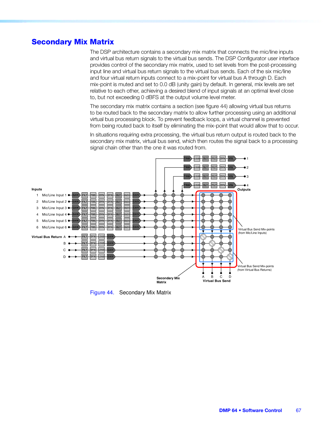
Secondary Mix Matrix
Secondary Mix Matrix
Input 1 to Virtual Bus a
Group Members
Group Masters
Grouped Controls
Sample Fader Group Master and Associated Gain Controls
Configure a group as follows
Configuring a Group Master
Deleting a Group Master
Viewing and Using a Group Master
Add a Group
To delete a group
Clear All Groups
Tools
Increment/Decrement Simulator
To use the Increment/Decrement Simulator
Group Details Report
Soft Limits
To move the upper limit
To move the lower limit
Digital I/O Ports
Reinitialize Digital I/O
Emulate Mode and Live Mode
Synchronizing Pull From or Push To the DMP
To remove a digital I/O script from the DMP
To switch from Emulate mode to Live mode
Selecting Live Mode and Pushing or Pulling Data
If USB is selected in step
If RS-232 is selected in step
Selecting Live Mode
Yes or No
Previewing and Recalling a Preset
Presets
Save Preset
Building a Preset
To save a preset use the following instructions
Presets Pull vs. Push or Create Live
Managing Presets
Save Protected Configuration
Protected Configuration
Recall Protected Configuration
Change PIN
Keyboard Navigation
DSP Configurator Windows Menus
Standard Windows Navigation
Tab key
DSP Configurator-unique Navigation
Saving a Preset Using Keyboard Navigation
Optimizing Audio Levels
Gain, Trim and Volume Controls
Setting Input Gain
About Setting Gain Structure
Setting a Nominal Output Level
Setting Output Gain Structure
Adjusting Pre-mixer Gain
Adjusting Trim
Setting Mic/Line Input and Mix Levels
Setting Volume Control for the Amplifier Stage
Connection Options
LAN port defaults
DMP 64 RS-232 protocol
USB port details
USB Port Front Panel
RS-232 Ports
Ethernet LAN Port
Ethernet Connection
Connection Timeouts
Verbose Mode
To establish a network connection to the DMP
Host-to-device Communications
Password Information
DMP 64-initiated Messages
Symbol definitions
Error Responses
Hex Unit response
Telnet Web Browser
URL Encoded Web Unit response
Command Ascii command URL Encoded Response
Command and Response Table for Basic SIS Commands
Command Ascii command Response Additional
Command and Response table for basic SIS commands
Description
EX3# CA
EX! CP
EX# NI
Command Ascii command Response Additional description
DSP Processors Addressable by SIS Commands
Command and Response Tables for DSP SIS Commands
Special Characters
Symbol definitions
Audio Level Control, and Mix-point Selection
Command and Response Table for DSP SIS Commands
EOX6%GRPM
X6 Level Control and Mix-point Selection
X7 Pcfg
DMP 64 SIS Programming and Control 108
Mix
X6! Mix-point gain C, and Post-mixer trim D level values
110
+18 2229 2230 2231 2232 2233 2234 2235 2236 2237 +19 2238
X6@ Mic/line gain a
113
Value
X6@ Mic/line gain a
Output Level Control
DMP
118
Value
Pre-mixer gain B, Virtual return gain F only
Download the Startup
Access the device using Html pages as follows
Connect To
System Status
Status Tab
System Settings
Configuration Tab
IP Settings Fields
MAC Address Field
Date/Time Settings Fields
Change a Password
Passwords
Clear a Password
Firmware Upgrade To update the device firmware
Firmware Upgrade
Location of Firmware Upgrade Files on the Website
Downloading Firmware Upgrade Files
DMP 64 Html Operation 130
File Management
File Management Tab
Upload your own file as follows
Change an input audio level setting as follows
Audio Settings
Control Tab
Change the Input Gain and Attenuation
Mute and Unmute the Mixer-points
Mute and Unmute Inputs and Outputs
Change the Mic Mix Audio Level
Change an output audio level setting as follows
Change the Output Volume Level
Group Controls
Presets
Presets
Firmware Loader
To access the firmware uploader
DMP 64 Reference Information 137
DMP 64 Reset Mode Summary
DMP 64 Hardware Reset Modes
UL Rack Mounting Guidelines
Tabletop Use
Rack Mounting
Furniture Mounting
Extron Warranty