DMP 64 specifications
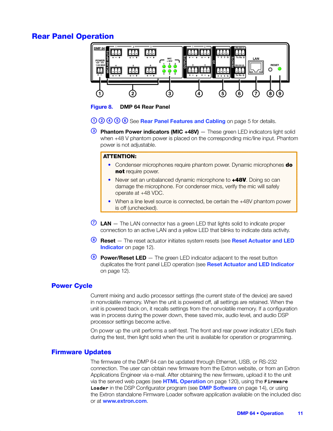
The Extron DMP 64 is a versatile digital matrix processor that is specifically designed for handling multi-channel audio signal distribution in a variety of applications. As a part of the Extron family of audio products, the DMP 64 is particularly well-suited for educational institutions, corporate environments, and other professional settings where high-quality audio management is paramount.One of the standout features of the DMP 64 is its six inputs and four outputs configuration, allowing users to mix and route audio signals with ease. This flexibility is crucial in environments like lecture halls or corporate meeting rooms where multiple audio sources may need to be controlled simultaneously. The DMP 64 supports a wide range of audio formats and operates seamlessly with both balanced and unbalanced audio signals. This ensures compatibility with various microphones, speakers, and other audio devices.
The technology behind the DMP 64 includes Extron's innovative ProDSP, which enhances audio processing capabilities. ProDSP allows for high-quality sound processing through advanced algorithms that provide features such as equalization, compression, and limiting. The processor also includes preset recall functionality, enabling users to quickly switch between different audio setups as needed. This can be particularly beneficial in dynamic environments where quick adjustments are often required.
Another important characteristic of the DMP 64 is its user-friendly interface. With intuitive controls that are easy to navigate, users can quickly access and adjust audio settings without the need for extensive training. The device supports Extron's Global Configurator and GUI Designer software, allowing for remote control and customization of the audio system easily. This integration is essential for system integrators who want to create tailored solutions for their clients.
The DMP 64 also features an integrated web interface, providing a convenient way to manage the system from any connected device. This capability makes troubleshooting and system management straightforward and efficient, especially for tech support teams who may need to address issues remotely.
In addition, the unit is designed with robust connectivity options, including Ethernet for control and monitoring, as well as standard audio inputs and outputs. Built with reliability in mind, the DMP 64 is housed in a sturdy chassis, ensuring it can withstand the demands of everyday use in professional settings.
Overall, the Extron DMP 64 combines advanced audio processing technology with user-friendly design and features that cater to the needs of today’s audio/video environments. Its flexibility, reliability, and high-quality sound management make it an ideal choice for diverse applications, from classroom environments to corporate meeting spaces. Whether it’s for conferencing, presentations, or events, the DMP 64 stands out as a powerful tool in professional audio management.

