Audio input and output connections (audio/video models)
The audio level for each input can be individually set, via the front panel or
By default, the audio follows the video switch. Audio breakaway, which is commanded via the front panel, under
5Balanced or unbalanced audio input connections (captive screw audio connector [A] models only) — Each input has a 3.5 mm,
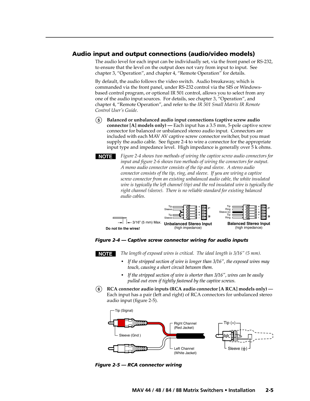
Figure 2-4 shows two methods of wiring the captive screw audio connectors for input and figure 2-6 shows two methods of wiring the connectors for output. A mono audio connector consists of the tip and sleeve. A stereo audio connector consists of the tip, ring, and sleeve. If you are wiring a captive screw connector from an existing unbalanced audio cable, the white insulated wire is typically the left channel (tip) and the red insulated wire is typically the right channel (sleeve). There is no reliable standard for existing balanced audio cables.
| Tip | L |
| Sleeve | |
|
| |
| Tip | R |
| Sleeve | |
|
| |
3/16” (5 mm) Max. Unbalanced Stereo Input | ||
Do not tin the wires! |
| (high impedance) |
Tip | L | |
Ring | ||
| ||
Sleeve (s) |
| |
Tip | R | |
Ring | ||
|
Balanced Stereo Input
(high impedance)
Figure 2-4 — Captive screw connector wiring for audio inputs
The length of exposed wires is critical. The ideal length is 3/16” (5 mm).
•If the stripped section of wire is longer than 3/16”, the exposed wires may touch, causing a short circuit between them.
•If the stripped section of wire is shorter than 3/16”, wires can be easily pulled out even if tightly fastened by the captive screws.
6RCA connector audio inputs (RCA audio connector [A RCA] models only) — Each input has a pair (left and right) of RCA connectors for unbalanced stereo audio input (figure
Tip (Signal)
Right Channel
(Red Jacket)
Tip (+)
Sleeve (Gnd )
Left Channel | Sleeve ( ) |
(White Jacket) |
|
Figure 2-5 — RCA connector wiring
MAV 44 / 48 / 84 / 88 Matrix Switchers • Installation |