Quick Start — MAV Series AV Matrix Switchers
Installation
Step 1 — Mount
If desired, mount the switcher in a rack with the supplied rack ears or mount the switcher under a desk using an Extron MBU 149 1U Enclosure
Step 2 — Inputs
As applicable to your switcher, connect:
a Up to 4 or 8
—or — Up to 4 or 8 composite video inputs to the input connectors.
b Up to 4 or 8 unbalanced stereo audio inputs to the input RCA connectors.
— or — Up to 4 or 8 balanced or
unbalanced stereo audio inputs to | L | 1 R |
the input captive screw connectors.
Step 3 — Outputs
As applicable to your switcher, connect:
a Up to 4 or 8
b Up to 4 or 8 unbalanced stereo audio devices to the output RCA connectors.
— or — Up to 4 or 8 balanced or unbalanced
stereo audio devices to the output | L | 1 R |
captive screw connectors.
CAUTION Connect the sleeve to ground. Connecting the sleeve to a negative
damage the audio output circuits.
Tip | Tip |
See caution | Ring |
Sleeve | Sleeve (s) |
Tip | Tip |
See caution | Ring |
Unbalanced Output | Balanced Output |
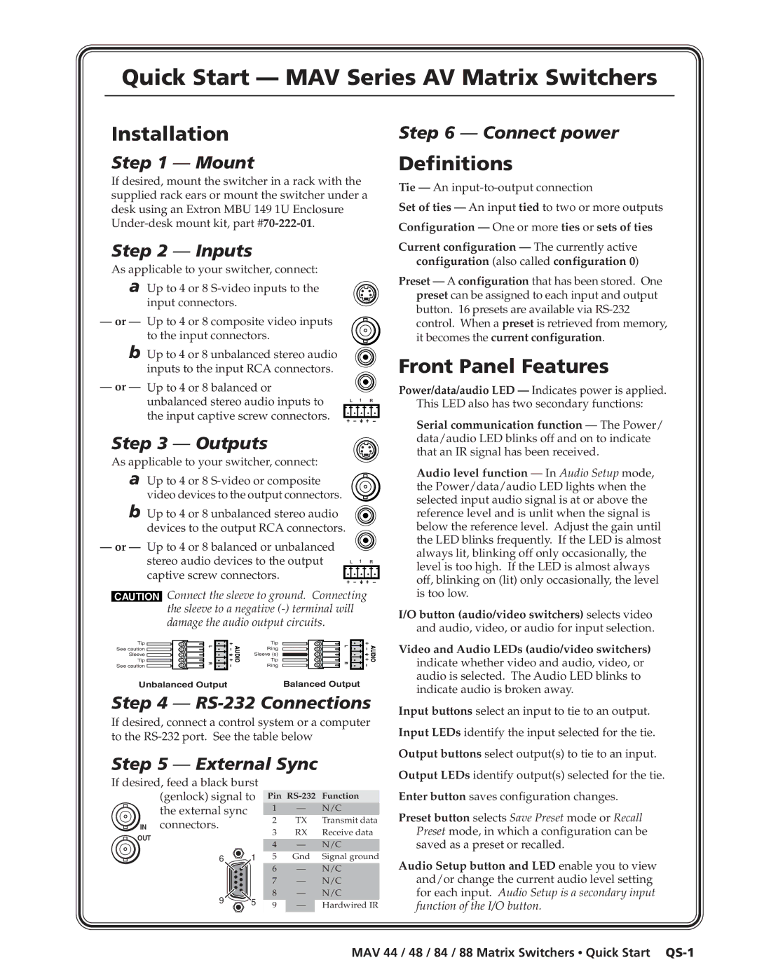
Step 4 — RS-232 Connections
If desired, connect a control system or a computer to the
Step 5 — External Sync
Step 6 — Connect power
Definitions
Tie — An
Set of ties — An input tied to two or more outputs
Configuration — One or more ties or sets of ties
Current configuration — The currently active configuration (also called configuration 0)
Preset — A configuration that has been stored. One preset can be assigned to each input and output button. 16 presets are available via
Front Panel Features
Power/data/audio LED — Indicates power is applied. This LED also has two secondary functions:
Serial communication function — The Power/ data/audio LED blinks off and on to indicate that an IR signal has been received.
Audio level function — In Audio Setup mode, the Power/data/audio LED lights when the selected input audio signal is at or above the reference level and is unlit when the signal is below the reference level. Adjust the gain until the LED blinks frequently. If the LED is almost always lit, blinking off only occasionally, the level is too high. If the LED is almost always off, blinking on (lit) only occasionally, the level is too low.
I/O button (audio/video switchers) selects video and audio, video, or audio for input selection.
Video and Audio LEDs (audio/video switchers)
indicate whether video and audio, video, or audio is selected. The Audio LED blinks to indicate audio is broken away.
Input buttons select an input to tie to an output.
Input LEDs identify the input selected for the tie.
Output buttons select output(s) to tie to an input.
If desired, feed a black burst (genlock) signal to the external sync
IN connectors.
OUT
6 1
9 5
Pin
1 | — | N/C |
2 | TX | Transmit data |
3 | RX | Receive data |
|
|
|
4 | — | N/C |
5 | Gnd | Signal ground |
|
|
|
6 | — | N/C |
7 | — | N/C |
8 | — | N/C |
9 | — | Hardwired IR |
|
|
|
Output LEDs identify output(s) selected for the tie.
Enter button saves configuration changes.
Preset button selects Save Preset mode or Recall Preset mode, in which a configuration can be saved as a preset or recalled.
Audio Setup button and LED enable you to view and/or change the current audio level setting for each input. Audio Setup is a secondary input function of the I/O button.